Eddy Wireless SD Cards Series User Manual Download Page 24

W 2 0 1 2 P

CHAPTER 4: COMMON SHORTCUT SETUP

4.1

CABLES TESTING AND POWER ON

The host power cable has three wires red, black and yellow. Red and black wires connect to the car
battery directly,red wire to positive pole and black to negative pole.The yellow wire directly connects
to the ignition wire (namely the gear before the start-up motor). However, during test in other places
without vehicle environments, the wiring connections are as follows: twist the red and yellow wires 
into one thread and connect to positive pole, while black wire alone to negative pole,then provide 
DC12V-5A or above switching power supply to the host.
    
1: Properly connect the power cable and power it. As long as the power supply is provided, the 
blue lamp of the panel

PWR is on, and the device stays at stand-by mode. 

2: Connect the monitor and other relevant equipments to the host via the AV-OUT cable. Make sure
 all cables are correctly connected.
3: The device can be switched on only when being locked with the electronic key, and all other 
corresponding indicator lamps flash yellow after booting.
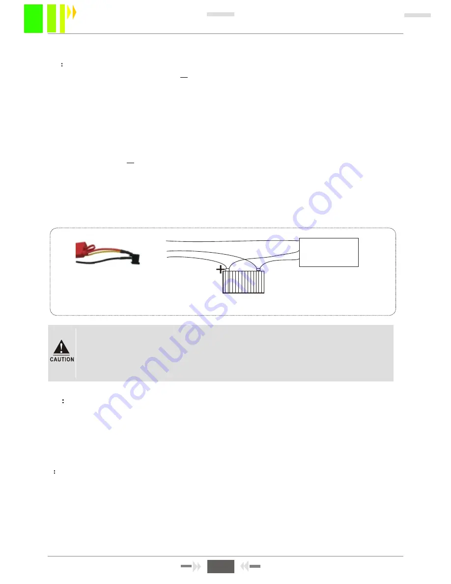
The below Figure 4-1 shows the testing cable, and vehicles actual power cable connection:

"

"

'

Test cables

Vehicle control
circuit

Red cable

Black cable

Yellow cable

Vehicle Battery

-

1. The voltage range of power supply is DC8-36V. When only the blue lamp of the 

front panel flashes on, the device stays at stand-by mode. And more than just one 

lamp will be on after normal booting.

2. If power supply is provided via the testing cable, the host can t realize 

power-off delay.

'

Figure 4-1 Vehicle wiring diagram

4.2

RECORDING SETUP

1:AUTO RECORDING

With SD card installed, the device will start recording automatically after normal boot into the system, 

without any setting changes. And DVR will operate according to ex-factory default settings.

NOTE

During the first use after booting into the system, formatting the installed SD card is 

recommended, so that the system can be more compatible to its format.

2

TIMED  RECORDING

MENU -RECORD  SETUP-NORMAL SETUP--REC  MODE

, and change into Timed Record, then 

back to the upper menu

TIMED  SETUP

and setup the recording time range, then save. For more

detailed menu operations, please refer to Section 3.4-3. 

NOTE:


Use the key + or -  (under the number 8 or 9 ) during the recording time range

setup.

3:ALARM RECORDING
MENU -RECORD  SETUP-NORMAL SETUP--REC

  Mode, then change into Alarm record. Setup the

"

"

" " " "

" " " "

22

SD Card Mobile DVR User Manual

22

Summary of Contents for SD Cards Series

Page 1: ...W 2 0 1 2 P SD Cards Series MDVR USER S MANUAL NO W2012K0101P002 V1 07E V1 07E IRELESS I sales eddywireless com...

Page 2: ...3 4 1 Mormal setup 3 4 2 Channel setup 3 4 3 Timing setup 3 4 4 Sub stream setup 3 5 Vehicle information 3 5 1 Sensor setup alarm input 3 5 2 G Sensor setup 3 5 3 Speed setup 3 6 TOOLS 3 6 1 Format di...

Page 3: ...deo format Video stream Specifications Chinese English Graphical User interface OSD menu Users Password Administrator Password 4CH VIDEO INPUT 1 0Vp p 75 1CH VIDEO OUTPUT 1 0Vp p 75 1 CH 4 CH Preview...

Page 4: ...Items 12V 4V 5V 75 4V 4V 40 80 Specifications 8V 36V When long term under 8V or long term over 36V auto power off and enter protection mode 12V 0 2V Max 2A OFF On 75 for each video input impedance Inp...

Page 5: ...tallation part Equipment installed on the plane should remain a distance of 6 inches 15 centimeters away from other objects to assure the air flow and heat dissipation Don t install it on the enclosed...

Page 6: ...lock in working period the system will upload the SD card delay power off according to the menu setting SD 1 SD 2 Figure 2 2 Push the card s protection cap towards right after unlocked 128 5 162 47 80...

Page 7: ...xtension interface VIDEO output interface Audio output interface Bus interface Sensor interface Bus Speed pulse input interface RS485 RS232 interface Speaker interface Name WIFI GPS 2G 3G DC8 36V MCU...

Page 8: ...en all the dashboard light the gear before start the motor Power cable 4PIN A V test cable Alarm cable RS485 RS232 SENSORS SPEED 1 Ensure the battery voltage is between 8V 36V before connection Otherw...

Page 9: ...tput interface simple type has only two alarm inputs Alarm input detection are all level detection It can connect to various vehicles driving status such as brakes turns door switches buttons of emerg...

Page 10: ...ress theplay key to return to the normal playing speed Playing back It can jump to point time to start playing Press this key to frame Button to play The forward button when playback video material Th...

Page 11: ...enu but can not set the menu and data Admin gets the permission to modify the system parameters PASSWORD Enter password according to the selected user name When password is correct select down button...

Page 12: ...then press or to set the data press enter to confirm 3 During operation timeout can set from 30 3600 seconds and device number modification press CANCEL to delete and then press the number button Figu...

Page 13: ...on the device will start working Recommend to select it as the default mode Timing mode means the device will turn on or power off during the fixed time 2 Delaying off setting when select ACC mode or...

Page 14: ...to the Alarm recording 0 60s range 6 ALARM REC DELAY S After the alarm stops it will keep recording a period of time and pack into the alarm recording 7 ALARM OUTPUT TIME S It means the alarm output t...

Page 15: ...s that need setup Setup each time according to the number key Time list Figure 3 15 Figure 3 16 Cursor move to the time then press plus and minus key to operate CHANNEL SETUP RES QUA HIGH LOW CH ENABL...

Page 16: ...off on thismenu Actually sensor input is also alarm input with high low level effective Users normally use above 5V high level to form the loop 3 5 1 SENSOR SETUP ALARM INPUT Figure 3 19 3 5 2 G SENS...

Page 17: ...EED SETUP Figure 3 22 GPS VEHICLE KM KM MPH 1 When setting GPS VECHILE to get the speed please press ENTER to switch if select GPS so should require demo have GPS module and with signal that can pass...

Page 18: ...on area then save Motion Detection 3 6 2 CONFIGURE MANAGE AND LOG SEARCH Configure manage mainly including import and outport system current configuration and restore factory configuration If operates...

Page 19: ...status only can detecting the moving objects Figure 3 30 Figure 3 31 PROCEDURES OF SETTING DETECTION AREAS No effect on this menu the procedures are as bellowing Step1 Copy upgrading file HI3512 wkpm...

Page 20: ...type if the demo support WCDMA then select WCDMA Otherwise if it is EVDO then select EVDO Press the remote control key ENTER to switch Support WCDMA or EVDO it is depends on the model type every demo...

Page 21: ...the center of the IPfield in Figure 3 10 enter the CMS center IP andport numbe r Figure 3 36 ENCRYPT TYPE WEP WIFI SETUP WIFI SETUP ENABLE ENCRYPT AUTH MODE ENCRYPT TYPE SSID PASSWORD ON IP ADDR NETM...

Page 22: ...or more detail information A SEARCH INSTRUCTIONS 8 Remote control opertation Setting on the manu They areused for controlled up down left and right ZOOM enlarge and narrow function Focus Transfer larg...

Page 23: ...the details in chapters 4 5 for reference Figure 3 42 setup Record mode Others manus such as sensor setting speed alarm setting shock acceleration motion detection set related parameters and also conn...

Page 24: ...ng cable and vehicles actual power cable connection Test cables Vehicle control circuit Red cable Black cable Yellow cable Vehicle Battery 1 The voltage range of power supply is DC8 36V When only the...

Page 25: ...io is determined according to the set speed and the obtained pulse during the course of vehicle s running so the operations are more complex A simplified connection is shown as Figure 4 3 Pulse sensor...

Page 26: ...oard Step 5 Three ways Cables connections Type 1 Connect the RS 485 control line on PTZ to the hosts RS485 A and RS485 B port respectively and video cable to the host video input port then provide pow...

Page 27: ...installation language which supports Chinese and English then click OK and click Next After the installation is completed the shortcut of player icon is on the desktop the installation steps are show...

Page 28: ...or the Simply MDVR which without WIFI and 3G modules the below instructions is not compatible to them Insert USIM card modify the DEV number modify the Vehicle number set the server IP address and por...

Page 29: ...local area network via PC ping Step 6 Above are two ways networking mode 3G or WIFI After network connection the next step is CMS management software operation on the PC there are two steps One is CM...

Page 30: ...g channel is switched off if timing record is set the device will not record as it is not in the recording time 4 Check whether the SD card is pulled out with power on or not Suggest to pull out SD ca...

Page 31: ...ure the center server is working and on network And then check whether the device number has been occupied and has caused conflicts then check whether center number and APN set correctly or not Check...

Page 32: ...l per hour is as showing as the above table for reference The actual recording file size is depending on the current channel illumination variant object movement and many other factors If the image is...

Reviews: