background image


EcoFoot5D Install Guide V1.1-FINAL 


Page 6 of 19


January 25, 2018, ES10560 


ecolibriumsolar.com 


This install guide officially documents the components used and proper methods for an EcoFoot5D installation. 
Bonding elements are incorporated into EcoFoot5D components. As the system is built on the roof, 
components and modules are bonded together. Specific steps to ensure a bonded system are described through 
the installation guide. It is the installer’s responsibility to ensure that the system is safely and properly installed, 
and that the system is bonded back to a final ground point. 

When wiring the array, keep bare copper from contacting bare aluminum. 

Thermal and Seismic Design Requirements: 

EcoFoot5D is a flexible and expandable design that 

accommodates various array geometries.  
Maximum widths for arrays are as follows:  


60-cell modules, 26 modules in a row 


72-cell modules, 22 modules in a row  

Minimum spacing between sub-arrays is 6”.  Site specifics may further limit array sizes and spacing.   

Seismic and Uplift Design Requirements: 

EcoFoot5D can be attached when required by seismic and uplift 

conditions as specified by the Authority Having Jurisdiction (AHJ). Addendums in this install guide document 
the components used and proper methods for an EcoFoot5D installation with attachments. Use the method 
required for the specific Fire Code Rating of the PV module. 

Re-Inspection:

 Ecolibrium Solar recommends periodic re-inspection of the installation for loose components, 

loose fasteners, and any corrosion, such that if found, the affected components are to be immediately replaced. 

Compatible Modules:

 Ecolibrium Solar has evaluated many photovoltaic modules for installation compatibility 

with the EcoFoot5D ballasted racking system.  A list of compatible modules may be found in “EcoFoot5D Install 
Guide Appendix - Compatible Modules.pdf” on our website:  www.ecolibriumsolar.com 

UL2703 Qualification:

 In cases where UL 2703 certification is required, the EcoFoot5D system conforms to the 

UL2703 Standard for grounding and bonding and fire ratings.  The EcoFoot5D system may be used to ground 
and/or mount a PV module complying with UL1703 only when the specific module has been evaluated for 
grounding and /or mounting in compliance with the included instructions. 

EcoFoot5D Racking maintains a Class A fire rating when installed in landscape orientation according to the 
installation instructions, on a low slope roof Class A roof with Type 1 and Type 2 modules. When installing Type 
2 modules a Ballast Tray is required. For roofs with lower fire ratings, the existing rating is maintained when 
EcoFoot5D is used. 

At this time, the EcoFoot5D system is undergoing further testing pertaining to mechanical loading with specific 
modules. Further information about Ecolibrium Solar’s UL2703 conformance may be found in “EcoFoot5D 
Install Guide Appendix - UL2703 Qualification.pdf” on our website: www.ecolibriumsolar.com 

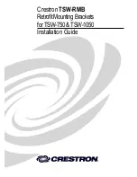
UL2703 System Label:

 The label shown below is stamped into to the Wind Deflector (identified as component 

5 in the installation guide). 


The Date Code ABCYZZ shown above will appear on production parts, letters defined as follows: 


ABC shall be an acronym for identifying the source factory 


Y shall be the Quarter of the year (i.e. 1, 2, 3, 4) of manufacture 


ZZ shall be the last 2 digits of the year of manufacture


Summary of Contents for EcoFoot5D

Page 1: ...riumSolar com Field Support 866 488 6794 FieldSupport EcolibriumSolar com www ecolibriumsolar com Installation Guide Installation Guide EcoFoot5D High Density 5 Degree Ballasted Racking System Document No ES10560 Rev 1 1 January 2018 ...

Page 2: ...ide V1 1 FINAL Page 2 of 19 January 25 2018 ES10560 ecolibriumsolar com Revision History Revision Description of Changes Date 1 0 Initial EcoFoot5DTM Release 2017 September 05 1 1 Add Attachment Appendix B 2018 January 25 ...

Page 3: ...sibility 4 Disclaimer of Liability 4 Warnings Safety 5 EcoFoot5D General Application Notes 5 EcoFoot5D Core Components 7 Install EcoFoot5D in 6 Simple Steps 8 Appendix A Grounding Bonding 11 Appendix B Roof Attachment Methods 12 Legal Notices 2017 Ecolibrium Solar Inc Ecolibrium Solar and EcoFoot2 are registered trademarks of Ecolibrium Solar Inc EcoFoot5D is a trademark of Ecolibrium Solar Inc re...

Page 4: ...ty equipment as required by applicable rules and regulations Complying with all applicable local and national building codes including any that may supersede this manual Ensuring that Ecolibrium Solar EcoFoot5DTM and other products are appropriate for the specific installation and are designed for the installation environment Ensuring that the roof its rafters connections and other structural supp...

Page 5: ...hen working with or near electrical systems Always provide OSHA approved fall protection for all installation personnel Never wear jewelry during mechanical and electrical installation work Never work in rain snow or extremely windy conditions Never leave a module unsupported or unsecured on the roof Never install broken photovoltaic modules EcoFoot5D General Application Notes Site Specific System...

Page 6: ...e to be immediately replaced Compatible Modules Ecolibrium Solar has evaluated many photovoltaic modules for installation compatibility with the EcoFoot5D ballasted racking system A list of compatible modules may be found in EcoFoot5D Install Guide Appendix Compatible Modules pdf on our website www ecolibriumsolar com UL2703 Qualification In cases where UL 2703 certification is required the EcoFoo...

Page 7: ...coFoot5D Base 2 Universal Clamp Lower 3 Universal Clamp Upper 4 Clevis Pins 5 Wind Deflector 6 Ballast Tray 7 Mid Support Upper 8 Mid Support Lower 9 5 16 Thread Forming Screw Hardware Required All required hardware is included Tools Required Deep Socket Calibrated Torque Wrench Torque Settings 14 ft lbs on all Fasteners ...

Page 8: ...ocker Step 2 Position Array 2 1 Snap two chalk lines on roof denoting outside edges of the EcoFoot5D Bases per project drawing Start from the north or south edge Ensure chalk lines are square 2 2 Place EcoFoot5D Bases in approximate position throughout the array Installation Tips Only install Clamps where modules will rest See Step 3 for correct placement and orientation of Clamps Base Lower Clamp...

Page 9: ...e south row the Upper Mid Support will not be pressed onto a module frame On the north row the Lower Mid Support will not be pressed onto a module frame 4 3 Slide Upper and Lower Mid Support together using the male female features If required place optional self adhering EPDM pads on the bottom surface of the Upper and Lower Mid Supports Nut Base Module Nut PV Module Center Point Upper Lower Mid S...

Page 10: ...Kit Torque Screw to 14 ft lbs 5 3 Place ballast not included in a single layer evenly dispersed along the length of Ballast Trays Apply ballast per the ballast plan specified in the PE Certified Ballast Plan Sheet S 1 0 Step 6 Install Wind Deflector 6 1 Place Wind Deflectors into slot on EcoFoot5D Base and attach to Rocker using Nut provided 6 2 Torque Nut to 14 ft lbs using a deep socket Applicat...

Page 11: ...d Deflector a minimum of from any edge One Ground Lug is required for every 400 modules connected within an array Ecolibrium Solar recommends using 6 copper ground wire in conjunction with WEEB grounding devices such as the WEEB LUG 6 7 or WEEB DSK516 Lugs are a single use component Other grounding methods must be reviewed and approved by a licensed master electrician or electrical engineer and Au...

Page 12: ...ing Attachment Methods Seismic and Uplift Attachment Seismic Attachment Modules with Type 1 Fire Code Rating Use Attachment with Strut Modules with Type 1 2 Fire Code Rating Use Attachment with Ballast Tray Modules with Type 1 2 Fire Code Rating Use Attachment with Ballast Tray and Strut Attachment with Strut Attachment with Strut Components included in Kit 1 L Bracket 2 x3 Qty 3 2 Elevator Bolt 1...

Page 13: ...d Flange Nut 1 2 Roof Attachment Place L Bracket on Stud and secure with 3 8 16 Serrated Flange Nut Step 2 Install Flat Plate or Station Anchor Roof Attachment 2 1 Align L Bracket of Roof Attachment with L Brackets on Bases and install Roof Attachment on either side of the Mid Support Install Roof Attachment per Roof Attachment manufacturer s instructions Elevator Bolt L Bracket Flange Nut Line be...

Page 14: ...ep 3 Attach Strut to L Brackets and Tighten Hardware 3 1 Secure Strut to L Brackets with 3 8 16 Serrated Hex Bolt and 3 8 16 Strut Nut Engage grooves of Strut Nut with the two lips within Strut 3 2 Tighten and torque all hardware Torque 20 hardware to 8 ft lbs Torque 3 8 16 hardware to 14 ft lbs ...

Page 15: ...4 Bolt Serrated Flange 1 4 20 Qty 4 5 Nut Serrated Flange 3 8 16 Qty 2 Not Included in Kit Roof Attachment Flat Plate Optional Addition of Strut to Ballast Tray Components Included in Kit 1 Screw Sheet Metal 12 x Qty 6 2 Washer Fender ID x 1 OD Qty 6 Not Included in Kit Strut 1 5 8 x 1 5 8 Torque Settings 8 ft lbs for 1 4 fasteners 14 ft lbs for 3 8 fasteners 5 ft lbs for sheet metal screws Tools ...

Page 16: ...t Tray install Roof Attachment per manufacturer s instructions Note Position the attachment such that it can share the same slot with the Mid Support as shown Step 2 Install Mid Span Support 2 1 Refer to Step 4 of the Installation Guide to install Mid Span Support Step 3 Install Hardware on Attachment Stud 3 1 Install 3 8 16 Serrated Flange Nut and 7 16 ID x 1 OD Washer onto Roof Attachment stud L...

Page 17: ...ay Line up slots with attachment stud base hardware and Mid Support 5 2 Torque fastener into Mid Span Support to 14 ft lbs through slot on Ballast Tray 5 3 Fasten Ballast Tray to base with Washers and Serrated Hex Bolts on both bases Torque to 8 ft lb 5 4 Install Washer and Serrated Flange Nut onto Preferred Roof Attachment in order shown below Torque Serrated Flange Nut to 14 ft lbs 5 5 Roof Atta...

Page 18: ...length of Ballast Trays centering Strut over Roof Attachment 6 2 Install two Sheet Metal Screws and Fender Washers on either side and as close to the roof attachment stud as possible Install additional screws along the length of the strut at no more than 24 intervals Strut reinforcement attachment complete Sheet Metal Screws with Fender Washers installed along the length of the strut at no more th...

Page 19: ...ecolibriumsolar com Strut Installation Note Strut may need to be cut and or spliced to meet the attachment requirements in the project s Ballast Layout Plan or engineering report Splice Strut and install hardware as shown All hardware is included in the Strut Kit Splice Kit ...

Reviews: