


P a g e
|
5
Version10- March 2017
Eco Pacific Pty Ltd
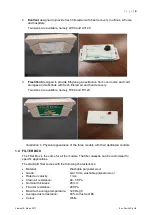
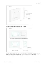
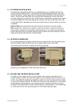
Below are the illustrations of Filter Boxes with 6 inch and 3 inch outlets for duct connections
to the HRV cabinet.
Illustration 2 - Air Filter Boxes with 6 inch and 3 inch outlets
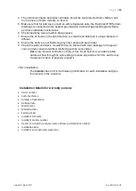
1.5 WALL CONTROLLERS
The standard Wall Controller is a 240 V switch fitted with a filter sensor light. If the filter is
blocked, the light will turn Red. The Optional Wall Controller is fitted with C0
2
sensor,
motion sensor, and filter sensor, and operates the EcoVent model of the fresh air HRV.
Illustration 3: Standard Wall Controller (left).
Illustration 4: Optional Wall Controller for EcoVent CO
2
sensor (right).
1.6 AIR FLOWS
AV80, EV80, and FV80 provide air flows of 80 l/s at 100 Pa external static pressure (ESP).
AV120, EV120, and FV120 provide air flows of 120 l/s at 100 Pa ESP.
Note
the
Filter Sensor
is fitted to the standard switch to operate the AussiVent and
FreshVent models, however the EcoVent is operated by an Optional Wall Controller.
1.7 OPTIONS
The Wall Controller can be fitted with;
CO
2
sensor
to measure the Carbon dioxide level in the room air and auto-activate the
ventilator with low, medium and high level indicators.
PIR (Photo Infrared) sensor
to
register any motion surrounding the Wall Controller and
auto-activate the ventilator as may be required in schools, board rooms, hospitals, and
clinics etc.
Filter Sensor
to measure when the filter is above 80% blockage, and turns the LED on the
Wall Controller to Red to alert the user to clean the filter.


