


P a g e
|
11
Version10- March 2017
Eco Pacific Pty Ltd
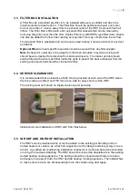
3.7 DIRECTION OF AIR FLOW
The units are marked with arrows for “Fresh Air Intake”, “Fresh Air Supply, “Room Air
Intake, and “Room Air Exhaust”. The ducting should be connected according to these
markings. The exhaust air outlet should be at least one meter away from the fresh air
intake of the Filter Box.
3.8 CONDENSATE DRAIN DISCHARGE
The AV and EV series ventilators are for indoor air stand-alone applications and do not
have a condensate drain discharge. However, the FreshVent models are for cold room
applications, where dry bulb temperature of one air stream goes below the dew point of the
other air stream and may condense, hence HRV is fitted with a condensate discharge. The
FreshVent HRV must be installed slightly sloped towards the drain outlet and fixed on a
solid base or steel angle brackets. This is to allow water to drain from the HRV and be
safely discharged to the nearest drain point.
The drain discharge is a half inch outlet and should be vented to the highest point to release
any trapped air. The drain pipe should have gravity fall of at least one inch for every 3
meter length of the drain pipe to the nearest down pipe to the ground. Comply with local
authorities in regards to drain discharge.
3.9 ELECTRICAL REQUIREMENTS
All the HRV models are fitted with fixed single speed direct drive motor and fan wheels, with
one fan at each end at the base for suction from outdoor air and indoor air.
All the models need a 10 Amp, 240V switch with general purpose outlet (GPO) located
within 1.5 meter from the unit for installation and operation. For connecting the HRV to
existing installations, a qualified electrician has to be consulted to ensure compliance with
the local wiring codes specified by the local electrical authorities.
Approximated Amps consumption for all the models:
Rated:
0.6 Amps
Running: 0.5 Amps
Wiring
The colour coded wires for the motors with their interconnections are shown below in the
wiring diagrams of illustrations 8 and 9.
4. COMMISSIONING
1. Ensure system is switched off at power board and unplugged.
2. The HRV is attached securely to the bracket, and the bracket is fastened to the hard
floor, roof, or wall or on a hard stand.
3. Make sure the filter is connected and all ducts are well harnessed on the collars with
duct tape.


