Firmware V6.6.9
29.07.2020
101/147
4 - Configuration System Centre
6 Measuring points
Configuration of the measuring points
7 Alarm is signalled
Configuration of the alarm signalling
8 Date / time
Setting of date and time
9 Firmware Update
Update of the firmware and the bootloader
10 System Information
System information
11 System Reset
Reset system
12 System upgrade
System upgrade
Menu 4-1-1 - Expansion System Centre
The entry screen for expansion of the system centre is called using this button.
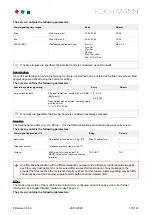
The screen contains the following parameters:
Expansion System Centre
Entry
Default
Number of SIOX modules X
Number of connected SIOX extension
modules
1 .. 4
0
Number of GLT PLC modules X
Number of available DDC modules in the
system (X = 1 .. 4, read-only)
Note: Only visible if DDC modules are also
connected!
0..4
0
Operating mode for the 2nd CAN bus
interface
Setting of the operating mode for the 2nd
CAN bus interface
--, repeater
--
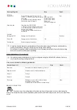
Sync input
Specification where the sync input for
energy record is applied
1)
.
-
Sync
input
Module
Module
1)
to which the message / alarm
signal is applied
SIOX1 ..SIOX4
-
Submodule XX
Submodule
1)
to which the message / alarm
signal is applied; this is ONLY visible
if module=DDC1..DDC4 has been selected
1..4
-
Input XX
Input
1)
to which the message / alarm signal is
applied
1..12
-
1)
Designations of the supported modules / inputs:
CI 4x00 system centre, internal inputs IN1 / IN2 (terminals A1, A2 / B1, B2)
SIOX1 1st extension module, inputs 1 .. 12
SIOX2 2nd extension module, inputs 1 .. 12
SIOX3 3rd extension module, inputs 1 .. 12
SIOX4 4th extension module, inputs 1 .. 12
DDC1 1st GLT DDC module 1
DDC2 2nd GLT DDC module 2
DDC3 3rd GLT DDC module 3
DDC4 4th GLT DDC module 4


