EBARA ESA500W Instruction Manual Download Page 9


vii


PM10U         


EBARA 

CORPORATION 

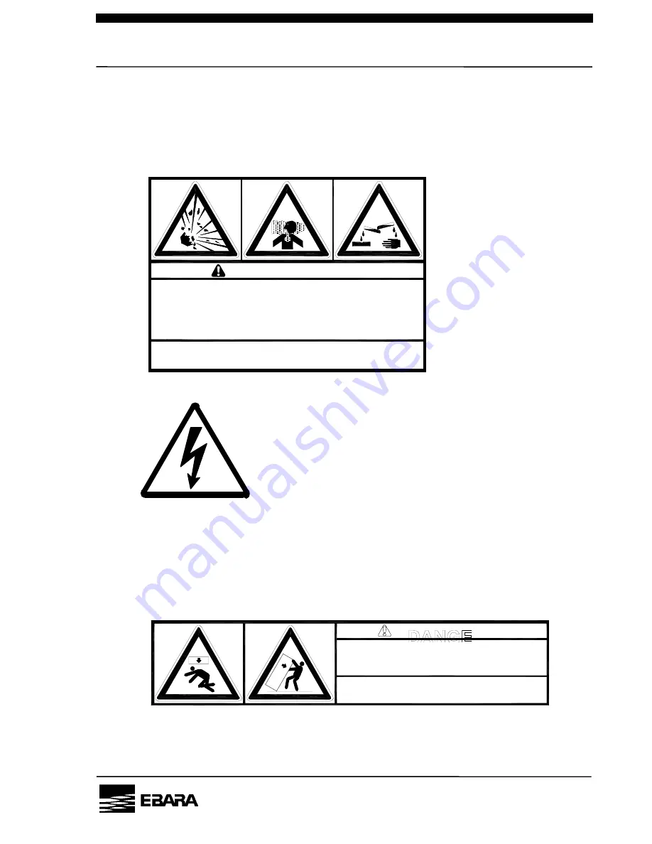
            3.    Hazardous materials warning 
 

      In case of hazardous materials are handled. Run the pump only with 


      N2 gas purge before servicing. Take adequate measures against 


      dangerous reaction and contact with human body. 


    4.    Electric charge mark 


            5.    Hazardous weight danger 
 

      Heavy weight may cause severe injury or death due to overturning 


      or falling pump. Keep out from under the lifted pump.     


      Raise all adjuster-feet fully when moving. 


WARNIN


Hazardous Materials 

Exposure to air may cause spontaneous fire or explosion. 
Inhalation or skin absorption will cause severe injury or 
death by poisoning. 
Purge thoroughly with nitrogen for at least 30 minutes 
before servicing. Use personal protective equipment 

appropriate to the materials to prevent exposure.

危険物質あり。


危険反応・人体への接触により重傷または死亡の危険があります。N2パージのみで30分以上


空運転を行なってから、危険物質のMSDSに従ってメンテナンスをして下さい。


C-7110-314-0001


Heavy Object 
Can cause impact injury through falling or tipping. 
Use appropriate, properly rigged lifting equipment and keep from
under suspended pump. Raise all adjuster feet fully when moving.

重量物。落下及び転倒により重傷または死亡の危険があります。 
吊り上げたポンプの下に入らないで下さい。 
移動時は全アジャスタフットを上限まであげて下さい。


C-7110-316-0001

Summary of Contents for ESA500W

Page 1: ... read and understand this INSTRUCTION MANUAL thoroughly before using this equipment Be sure to keep this INSTRUCION MANUAL on hand for future reference To Facility and Tool Manufactures Be sure to distribute this INSTRUCTION MANUAL to all end user personnel actually operation this equipment Model ООО in this INSTRUCTION MANUAL is our model code ISSUED BY PRECISION MACHINERY COMPANY ...

Page 2: ...nual without permission Manufacturer reserves the right to discontinue or change any specifications or designs without notice and without incurring obligations Model OOO in this catalog is our model code All rights reserved copyright EBARA Corporation ...

Page 3: ...romote harmony between technology and nature prevent environmental pollution and improve the overall results of our environmental management activities We are aware that environmental protection and management activities are the responsibility of all managers and employees of the Corporation and each person will demonstrate this awareness when carrying out his or her duties We will widely publiciz...

Page 4: ...s issued by EBARA in detail If you have any questions on pump operation safeties and maintenance please do not hesitate to contact EBARA directly Refer to Global network for contact address Three terms designating the level of hazard are used in this manual DANGER Indicates an imminently hazardous situation which if not avoided will result in death or serious injury WARNING Indicates a potentially...

Page 5: ...tenance work Do not switch on the power supply to the pump until work is completed WARNING Supply N2 gas to the exhaust piping when necessary to dilute the inflammable or toxic gas up to a safe concentration WARNING Purge with sufficient N2 gas before removing and washing the vacuum and exhaust piping Do not let inflammable toxic or dangerous materials disperse and guard against contact with the h...

Page 6: ...ng for gas leaks by pressurization please pressurize by less than 0 05 MPa into the purge port and do check WARNING Do not alter the pump member nor change any parts without the EBARA s consent or approval WARNING The pump casing and exhaust piping become extremely hot during operation and for some time after stopping Be sure that pump and exhaust piping do not come in contact with humans or infla...

Page 7: ...le process gases in the pumps and the pump is not equipped with a protection against the dangers from such pump usage The tool suppliers and users must pay attention not to simultaneously inject or mix those gases WARNING Do not perform a withstand voltage test Failure to comply could result in damage to the sensitive devices CAUTION Never operate the pump without pump cover for safety ...

Page 8: ...ng to cool before servicing 2 Hazardous voltage warning Hazardous Voltage may shock burn or cause death Turn power off and lockout before servicing WARNING 警 告 Hot Surfaces Will burn skin on contact Allow piping and casing to cool Before servicing 高温部あり 接触すると火傷をする危険があります 配管 ケーシングが冷えてからメンテナンスをして下さい C 7110 312 0001 WARNIN 警 告 Hazardous Voltage Contact will cause injury or death by electrical shock D...

Page 9: ...xposure to air may cause spontaneous fire or explosion Inhalation or skin absorption will cause severe injury or death by poisoning Purge thoroughly with nitrogen for at least 30 minutes before servicing Use personal protective equipment appropriate to the materials to prevent exposure 危険物質あり 危険反応 人体への接触により重傷または死亡の危険があります N2パージのみで30分以上 空運転を行なってから 危険物質のMSDSに従ってメンテナンスをして下さい C 7110 314 0001 危 険 Heavy...

Page 10: ... viii PM10U EBARA CORPORATION Location label ...

Page 11: ...of the warranty beyond the original period For repairs not covered under this Warranty EBARA will charge the customer for parts and labor Exclusions and Limitations This Warranty does not cover the following 1 Failure due to operating the pump in a manner or under conditions other than as described in the instruction manual 2 Failure due to corrosion byproducts or foreign material entering the pum...

Page 12: ...ust 4 3 2 Control System 4 3 2 1 Warning 4 3 2 2 Operation Status Control 5 3 3 The way of pump moving 5 3 3 1 Preparation 5 3 3 2 Moving method 6 3 4 Detailed Specifications 7 4 Installation 11 4 1 Movement and Fixation 11 4 1 1 Location 11 4 1 2 Caster and adjustment foot 11 4 2 Piping 13 4 2 1 Vacuum and Exhaust Piping 13 4 2 2 Cooling Water Piping 14 4 2 3 N2 Gas Piping 16 4 2 4 Ventilation Du...

Page 13: ...lay 40 6 6 Starting stopping the pump with the LCD controller 41 7 Operation 42 7 1 Before Starting 42 7 2 START STOP 44 7 2 1 LOCAL Start Stop 45 7 2 2 REMOTE Start Stop 46 7 2 3 COMMUNICATION Start Stop 47 8 Maintenance and Inspection 48 8 1 Internal energies 48 8 1 1 Power source 48 8 1 2 Cooling water 48 8 1 3 N2 gas 48 8 2 Routine Inspection 49 8 3 Vacuum and Exhaust Piping 51 8 4 Lubricant O...

Page 14: ...needed 2 Introduction 2 1 Introduction Check the following items on receipt of the pump package 1 Check that the nameplate affixed to the outer cover of the pump to confirm that the pump supplied agrees with your order Check the accessories against the packing list and the previously submitted drawings and documents to confirm that the all ordered accessories have been supplied 2 Check whether dam...

Page 15: ...iodically to operate the unit efficiently 3 To dispose the unit follow effective laws and ordinances applicable in the area where the unit is installed 4 To dispose the lubricant oil and chemicals follow effective laws and ordinances applicable in the area where the unit is installed WARNING If the pump becomes damaged during shipment or if parts are missing immediately contact EBARA If a leaking ...

Page 16: ...t the N2 gas line to the purge port provided according to the instructions in Table 3 1 and the descriptions in Section 4 2 3 In the cases the gas concentration may become higher than the specified for safe gas exhaust introduce the N2 gas to lines to the exhaust outlet The tool user shall provide the purge port for this purpose N2 gas is also required to supply to seal the shaft section This prot...

Page 17: ...d safety the condition of each utility and pump section is monitored by a sensor During pump operation all operating conditions are monitored including power supply cooling water flow N2 gas flow casing and motor coil temperature motor speed and motor current Continuous operation is possible when there is a momentarily power failure of 1 sec or less 3 2 1 Warning To assure the reliability of the p...

Page 18: ...t from the conventional pumps like as UERR A AA AAS series based on SEMI standard E73 3 2 2 Operation Status Control The sensor data are displayed on the LCD display provided on the controller to facilitate operation status control and daily inspection All WARNING and ALARM signals are displayed on the LCD display For remote operation and monitoring the signals are available as individual and grou...

Page 19: ...two persons shall move the pump by pushing its terminal portion alternately as directed below A B If pump needs to be moved on steps or ditches spread steel plate or the like which can sustain the pump weight over the steps ditches and pump shall be moved on it by two persons with care Steel Plate If pump should lose its balance when moving and start tripping over never try to sustain the pump get...

Page 20: ...ction 1 4 Tube Fitting Same as Swagelok Pressure Gauge Press Supply 0 15 0 7MPa Setting 0 09 0 12MPa N2 Gas Approx Flow rate 8 5 11 0 Pa m3 s Connection d 50 mm x L 50 mm Pressure 196 Pa Uti li ty Duct Venti Lation Approx Flow rate 0 5 m3 min Brand BARRIERTA J100ES NOK Lubrication Oil Quantity 1 5 L Approx Weight 750 kg 200V Model 3 Phase 200V 50Hz 200 220V 60Hz Phase Volt Freq 460V Model 3 Phase ...

Page 21: ...P 8 PM10U EBARA CORPORATION ...

Page 22: ...P 9 PM10U EBARA CORPORATION Fig 3 1 Model ESA500W Performance curve ...

Page 23: ...cuit Gas Outlet N2 Gas Flow Sensor Pressure Gauge P Regulator N2 Gas Motor Starter 1 Motor 1 Main Pump MP Motor Starter 2 Control Connector Circuit Breaker LCD Controller Cooling Water Flow Sensor Water FT2 FT1 Booster Pump BP Motor 2 Driver Silencer Fig 3 2 System Flow ...

Page 24: ...o the pump the distance between pump and interface box shall be 3m or less CAUTION Install pump in a location at an ambient not exceeding 30 C Particular caution is required when the pump is operated in an enclosed room CAUTION A gap of at least 50mm should be left open for ventilation between the pump cover and the adjacent equipment 4 1 2 Caster and adjustment foot Four integral mobile support u...

Page 25: ...it 1 To fix the pump turn the adjusters to the right to lower them 2 Level the pump by adjusting adjusters Check the levelness by a put level on the inlet flange If you cannot check the level you should keep a difference of height between the both sides of the pump base less than 1mm The adjustment allowance is approximately 15 mm NOTE If the pump is not leveled shortage of the lubrication oil sup...

Page 26: ...th a filter may be recommended c The weight of the pipes attached to the pump can cause misalignment and leaks from the flange connections Be sure that therefore to support the piping properly and not to apply undue force when aligning the flange faces It is recommended to insert flexible bellows when connecting the pipes to the suction and exhaust flanges of the pump The length of the flexible be...

Page 27: ...ty CaCO3 Hardness CaCO3 Evaporation residue Chlorine ion Iron Manganese ppm ppm ppm ppm ppm ppm ppm 20 6 5 8 0 75 120 250 80 0 3 0 2 Correct Wrong Socket Plug In Out Marking Sleeve Fig 4 2 Coupler CAUTION In the case of removing the coupler at first close the valve of cooling water supply line and next remove the coupler from the cooling water supply In the case of connecting the coupler connect i...

Page 28: ...and the flow is reversed a flow rate different from the normal value will be displayed Pump may not be cooled properly under this condition and this cause serious problem Be sure therefore to connect correctly to avoid problems CAUTION When the cooling water supply is left on while the pump is stationary dew condensation will form on the water cooled parts in locations with high humidity Make it a...

Page 29: ...Impurities of N2 gas may cause an accident when the pump is used for exhausting toxic and or inflamable gases 4 2 4 Ventilation Duct All dry pumps that Ebara supplies shall go through the leakage inspection after assembly regardless of the newly built or overhauled Yet in the cases where the user supplied line connection at the pump exhaust outlet came out or the connection became loose due to lon...

Page 30: ...ON For safety be sure to ventilate through the ventilation duct when the pump is used to exhaust toxic inflammable and or other hazardous gases Do not combine the ventilation duct with the pump exhaust piping CAUTION Even when the pump is used for exhausting process gases that are not toxic and or inflammable do not combine the ventilation duct with the pump exhaust piping The exhaust noise of the...

Page 31: ...RNING Electrical wiring shall be carried out only by qualified electricians CAUTION Do not apply the power supply from the pump s power pack to any other equipment as this will result in malfunctioning of the control units and in pump failure Control signal receptacle Power supply connector for accessory Drawer of power cable Earth Bar Inside of control panel Fig 4 4 Location of drawer of power ca...

Page 32: ...d ordinances DANGER Improper installation of the grounding plug can result in a risk of electric shock If repair or replacement of the cord or plug is necessary do not connect the grounding wire to either flat blade terminal The wire with insulation having an outer surface that is green with or without yellow stripes is the grounding wire Check with a qualified electrician or serviceman if the gro...

Page 33: ...ector for the main power supply and grounding Fig 4 4 and Tables 4 2 and 4 3 show the connector pin assignment Table 4 2 Pin Assignment of Power Supply Terminal Block No Phase A R B S C T D GND Fig 4 4 Power Supply Terminal Block As seen from connecting side Table 4 3 Terminal Block Specification Pump Model 200V Model 460V Model Adapted Terminal block M8 R S T M5 E Torque with a bundle R S T 8 0 1...

Page 34: ...Fig 4 5 15 Pin D Sub Miniature Female Receptacle As seen from connecting side Table 4 5 Control Connector Pin Assignment CN Z Pin No Signal name I O Signal type 1 MP START IN Run CLOSE Alternate 2 BP START IN Run CLOSE Alternate 3 MP START STATUS OUT Run CLOSE Alternate 4 BP START STATUS OUT Run CLOSE Alternate 5 WARNING STATUS OUT WARNING OPEN Alternate 6 ALARM STATUS OUT ALARM OPEN Alternate 7 R...

Page 35: ...SERVED IN 6 EMO STATUS OUT Abnormality OPEN Alternate 7 PUMP N2 WARNING STATUS OUT Abnormality CLOSE Alternate 1 8 RESERVED OUT 9 LOW SPEED CONTROL OUT LOW SPEED CLOSE Alternate 10 BACK PRESSURE HIGH WARNING STATUS OUT Abnormality CLOSE Alternate 1 11 RESERVED OUT 12 RESERVED OUT 13 14 RESET 15 SAVING ENERGY CONTROL 16 RESERVED 17 RESERVED 18 RESERVED 19 EMO STATUS 20 PUMP N2 WARNING STATUS 21 RES...

Page 36: ...CN Y Signal Contacts Input Signal 12VDC 1kΩ Open Collector Pump side Circuit Customer s connection Dry Contact 10mA Min Output Signal 100mA Max Pump side Circuit Customer s connection Open Collector 4VDC 27VDC EMO Dry Contact 100mA Max 4VDC 27VDC ...

Page 37: ...e an inductive load such as a relay be sure to insert a diode 100V 1A class in order to absorb the back electromotive force due to surge currents 5 Power Supply for accessories Power supply connector for accessory is equipped beside main power supply connector This power supply is used for standard option that is listed below Shall not be used for other purposes ADAPTER for Central Monitoring Syst...

Page 38: ... indication RESET For resetting WARNING and ALARM BZ OFF For buzzer mute in WARNING ALARM PRG For changing screen of pump status and change hierarchy of screen ENTER For using at DIP switch selection and change hierarchy of screen LED B P RUN BP running M P RUN MP running LOCAL LOCAL mode WARNING WARNING condition ALARM ALARM condition Fig 6 1 LCD controller ...

Page 39: ... R M A L P U M P R U N N I N G 3 Pump running history H I S T O R Y A L A R M W A R N I N G 4 Alarm history Indication of history H I S T O R Y U N I T N O 5 Pump unit No P U M P T Y P E V 6 Pump type Voltage O P E T I M E 7 Total operation time h B A C K P R E S S U R E 8 Back pressure option k P a P U M P N 2 F L O W 9 Pump N2 gas flow P a m 3 s W A T E R F L O W 10 Cooling water flow L m i n B ...

Page 40: ...ALARM has occurred Lower row displays details of WARNING ALARM 5 Total pump operating time gives the total hours of operation after shipment from the factory 6 The display will return to the electrical power and motor rotation speed indication when no operation takes place after the lapse of 1 minute 7 Use the Display Select Switch to change the display The WARNINGs ALARMs that have currently been...

Page 41: ...ewer Analog value Alarm 2nd code Alarm 1st code How to read the alarm history See Table 6 2 for the alarm codes ENTER 001 06 00 020901 12 23 21 Displayed during ENTER key pushed ENTER 002 51 00 020901 12 25 26 Displayed during ENTER key pushed WARNING BP MOTOR TEMP HIGH ALARM CASING TEMP HIGH UNIT NO OPE TIME h BACK PRESSURE kPa PUMP N2 FLOW Pam3 s WATER FLOW L min PUMP CASING C CONTROL LOCAL MODE...

Page 42: ... 24 00 Phase error 64 00 BP driver temp high case 02 BP driver OC 01 BP driver temp high inner 25 04 BP driver OV 02 BP comm error 02 BP driver OH1 04 IO comm error 03 BP driver OH2 05 Current IO comm eroor 26 07 BP driver CPF 06 BP current high 31 14 BP driver UV 07 indicates that the item is optional BP driver DRE 66 09 BP motor overload 2 67 00 BP motor step out 69 00 Emergency off 71 00 Water ...

Page 43: ...ning mode SET RUNNING MODE Switches the running modes NORMAL and S ENERGY Setting the rotational speed in the NOMAL mode SET BP NOMAL SPEED Sets the pump rotational speed in the NOMAL mode Setting the rotational speed in the LOW SPEED mode SET BP LOW SPEED Sets the pump rotational speed in the LOW SPEED mode Setting the pump N2 warning SET POINT N2 FLOW LOW Sets the WARNING value for N2 flow Setti...

Page 44: ...BP Normal rotational speed Setting the rotational speed in the LOW SPEED mode Setting the pump N2 flow low warning threshold Pressing the key PRG for 3 sec or more when the status screen is displayed switches to the operational mode setting screen When the mode you want to set is displayed press the ENTER to go to the setting change screen Fig 6 3 How to set the operational mode SET POINT BACK PRE...

Page 45: ...mode that is currently not set is displayed If you do not need to set press PRG key to go back to the previous screen 6 3 2 Setting the DIP switch See Section 6 4 for details of the DIP switch SET CONTROL MODE PRG PRG ENTER ENTER ENTER Setting done Setting done REMOTE MODE COM MODE The up and down arrow keys and turn On and OFF the DIP switch The key BZ OFF switches the selection from 1 to 8 A1 ON...

Page 46: ...min 1 Decrease the setting speed by 0 1 kmin 1 Upper limit 7 0 kmin 1 Lower limit 3 0 kmin 1 Factory Setting 7 0 kmin 1 6 3 5 Setting the rotational speed in the LOW SPEED mode Use the up and down arrow keys to change the setting value Increase the setting speed by 0 1 kmin 1 Decrease the setting speed by 0 1 kmin 1 Upper limit 7 0 kmin 1 Lower limit 1 0 kmin 1 Factory Setting 3 0 kmin 1 SET RUNNI...

Page 47: ... setting speed delay time by 0 1 Pam3 s or sec Upper limit 81 0 Pam3 s 60 sec Lower limit 2 2 Pam3 s 5 sec Factory Setting 5 0 Pam3 s 60 sec Reset value for WARNING set value of flow low 1 0 Pam3 s Use the keys and to set SET POINT N2 FLOW LOW PRG ENTER ENTER N2 FLOW LOW Pam3 s Setting done SET POINT N2 FLOW DLY ENTER ENTER N2 FLOW LOW DLY SEC Setting done SET POINT N2 WARNING ENTE PRG PRG ...

Page 48: ...rrow keys to change the setting value Increase the setting value by 0 5 kPa Decrease the setting value by 0 5 kPa Upper limit 20 0 kPa Lower limit 5 0 kPa Factory setting 10 0 kPa WARNING reset value Set value 2 0 kPa Use the keys and to set SET POINT BACK PRESSURE PRG ENTER ENTER BACK PRESSURE kPa Setting done ...

Page 49: ...atic operation External signal input OFF Optional Table 6 5 Dip Switch B Settings No Mode Off On Factory setting 1 2 3 4 Pump N2 valve control No Yes OFF 5 6 Remote Interface IF Exclusive special IF No use standard IF ON 7 Phase error monitoring Standard During starting only OFF 8 LCD screen initialize Carry out initialize Do not initialize OFF Optional Table 6 6 Dip Switch C Settings No Mode Off ...

Page 50: ...o Signal or PUMP STOP Regardless of External Signal PUMP STOP NOTE Dip switch A No 3 BUZZER and Dip switch B No 8 LCD initialize can change always When parameter setting of the dip switches other than dip switch A No 3 BUZZER is performed the LCD controller counts down 10 seconds the same as at the power on state right after the completion of the parameter setting DIP SW A No 5 Dip switch A No 5 l...

Page 51: ...this to ON to inactivate the interface default DIP SW B No 7 Selects the detection method for phase loss in the power source DIP SW B No 8 Locks or unlocks the currently selected operation status display which usually returns to the power display in 60 seconds DIP SW C No 1 This switch allows you to select NORMAL OPEN or NORMAL CLOSE for PUMP N2 WARNING output DIP SW C No 3 This switch allows you ...

Page 52: ...UT Dip switch B No MODE OFF ON 1 B1 NO ASSIGNED B1 NO ASSIGNED 2 B2 NO ASSIGNED B2 NO ASSIGNED 3 B3 NO ASSIGNED B3 NO ASSIGNED 4 B4 NO ASSIGNED B4 NO ASSIGNED 5 B5 NO ASSIGNED B5 NO ASSIGNED 6 Remote Interface B6 REMOTEI O OPTION B6 REMOTE I O STANDARD 7 Phase error monitoring B7 PHASE ERROR STANDARD B7 PHASE ERROR COUNTDOWN ONLY 8 LCD screen initialize B8 LCD DISPLAY INITIALIZING B8 LCD DISPLAY U...

Page 53: ... switches the dip switch numbers This sets the selected dip switch ON This sets the selected dip switch OFF ENTER This indicates the next page of the display DIP Switch A DIP Switch B DIP Switch C indicate the dip switch number 1 to 8 currently you are setting Fig 6 5 DIP Switch NOTE Duration of pump operation dip switches except A 3 BUZZER and B 8 LCD initialize can not be used for parameter sett...

Page 54: ... display screen 6 6 Starting stopping the pump with the LCD controller Maximum two LCD controllers can be connected Note only one of them can start and stop the pump the other shows the pump operational statuses The controller of which LED LOCAL is lit on has precedence over the other to control the start and stop operation If only one controller is connected the controller starts and stops the pu...

Page 55: ...connections Slowly turn the pressure adjustment knob clockwise to set the pressure gauge pressure to 0 1 MPa first Then press the red stopper to lock the knob in position WARNING Be sure to purge with N2 gas in order to prevent corrosion and reduce the formation deposition of reaction by products in the pump When inflammable and or toxic gases are diluted with N2 to the safe concentration be sure ...

Page 56: ...uge shows a reading of 0 09 0 12MPa 7 When the WARNING ALARM display appears on the LCD controller or when any abnormal symptoms are found other than the display take action in accordance with 10 Troubleshooting Even when the cause of the WARNING ALARM display has been removed it is maintained until the RESET signal is entered Either press the RESET button or enter an external RESET signal from th...

Page 57: ...0 minutes of stopping the process gases CAUTION Process gases will remain in the vacuum pipes and the pump even after the pump has been stopped Be sure that therefore to purge for at least 1 hour after the pumps has been stopped Do not discontinue the N2 purge when the pump is stopped only for a short time CAUTION The pump will remain at a very high temperature event after it has been stopped Be s...

Page 58: ...START button on the controller The Main Pump MP will start and the M P RUN lamp on the controller will light After this the Booster Pump BP will start automatically and the B P RUN lamp on the controller will light The current is indicated on the display during pump operation For other status display indications refer to Table 6 1 NOTE The pump will not start when an WARNING ALARM has been generat...

Page 59: ...BP is operated under external start signal input apply the external BP start signal to the control connector The current is indicated on the display during pump operation For other status display indications refer to Table 6 1 NOTE The pump will not start when a WARNING ALARM has been generated When a START signal is entered STARTFAIL will appear on the display b STOP Interrupt the external MP sta...

Page 60: ...l BP start command to the communication connector The power is indicated on the display during pump operation For other status display indications refer to Table 6 1 NOTE The pump will not start when an ALARM WARNING has been generated When a START signal is entered STARTFAIL will appear on the display BP can be started stopped by the external signal when the DIPswitch set accordingly b STOP Inter...

Page 61: ... dry pump is supplied with cooling water at pressure of maximum 0 4 MPa Disconnection of the cooling water resulted from improper handling may cause electrification and unit damage For service and transportation unplug the cooling water connection plugs on the inlet and outlet and seal off with plastic cap The self sealing plug is used for the cooling water connection plug in these pumps 8 1 3 N2 ...

Page 62: ...oil level gauge supply the lubrication oil See the Section 8 4 Lubrication oil when adding the oil WARNING Switch off the power supply to the pump first and interrupt the Earth Leakage Breaker ELB and lockout before you start on maintenance WARNING The pump and exhaust piping will remain at a high temperature during operation and for a short time after the pump has stopped Be sure to avoid contact...

Page 63: ... 1 cycle CAUTION When an ALARM signal has been generated in the REMOTE operating mode do not start the maintenance tasks until you have interrupted the external start signal When the external ALTERNATE start signal input is maintained the pump will start while the ALARM is being reset If any abnormal symptoms other than those displayed on the LCD controller appear take action in accordance with th...

Page 64: ...edictable reactions associated with the admission of air into the pump When checking for gas leaks by pressurization please pressurize by less than 0 05 MPa into the purge port and do check Toxic gases may be generated from by products in the piping or pump in pump disconnection from the tool piping for repair and replacement or flange removal for maintenance Gain relevant information about the pr...

Page 65: ... interior pump pressure has reached atmospheric pressure The chamber containing the oil is under low pressure vacuum so that a significant leak will occur causing substantial damage to the pump when the oil filling plug is removed with the pump operating CAUTION Waste oil shall be disposed of by industrial waste disposal dealer in accordance with Material Safety Data sheets appendix1 2 If the oil ...

Page 66: ...r inlet 5 Fit a waste oil container PVC bag to the bottom of the oil drain hole of the secondary reservoir and remove the drain plug See Fig 8 2 6 When you have drained off the waste oil close the drain hole after you have checked that there are no depositions and fragments adhering to the O ring attached to the plug Fig 8 2 Oil filler port oil level gauge and oil drain port positions 7 Please che...

Page 67: ...ubrication oil level exceeds the upper limit the oil may leak to the pump side Thus be sure not to exceed the upper limit line when adding the oil Except Booster pump gear side CAUTION When the lubrication oil level is lower than the lower limit line serious failure may be caused If you find out the shortage add the oil immediately Top line Bottom line ...

Page 68: ... 32X80L C 2244 031 0001 4 Recommendable Spare Parts Not needed for each pump Parts Name Type Order No Water flow sensor 20 L min C 5137 008 0001 N2 flow sensor 84 4 Pa m3 s C 5138 062 0111 N2 gas pressure regulator R31 200 C121 C 2250 101 0001 Following labels are attached to pump covers When they are hard to read for discoloring or peeling off please stick them again as directed Table 8 3 Labels ...

Page 69: ...posal regulations in each area Table 8 4 List of wastes during maintenance Part Equipped on Remarks Lubricant oil Inside of pump module See section 8 4 Refer to Appendix 1 2 for Material Safety Data Sheet Lithium battery CPU board No necessary to replace at usual maintenance Refer to Appendix 3 for Material Safety Data Sheet O ring Connection of vacuum line Usual industrial waste ...

Page 70: ...hese factories equip special tools sufficient evacuation duct Contact EBARA Sales office or Overhaul service center for detail To avoid dangers potentially encountered during pump overhauls follow instructions below to send your pump to an Ebara designated factory for overhaul or repair 1 Fill all necessary items in a form shown in Appendix 5 and fax it in advance to Ebara Service Center or one of...

Page 71: ...ork areas are at quarter or under the acceptable values specified using appropriate measurement equipment Without assurance of gas safety instruct the workers to wear proper personnel protective equipment if necessary to protect them from gas hazards The personnel protective equipment must include at least gloves safety goggles and a gas mask To disconnect and transport the pump proceed as follows...

Page 72: ...RNING For lifting the pump use only qualified operator personnel Be sure that the wire rope and crane used for lifting the pump are in proper order and match the weight of the pump To prevent unequal weight distribution suspend the pump by ensuring that the slinging angle remains symmetrically centered WARNING In case of sling and transportation be sure not to remain leaning more than 10 deg again...

Page 73: ...pump to avoid shock and position protective members between the outer cover and the wires in order to distribute the load of the fastening wires To avoid dangers potentially encountered during pump overhauls follow instructions shown in Section 8 7 Appendix 4 and 5 to send your pump to an Ebara designated factory for overhaul or repair ...

Page 74: ...operation and for some time after stopping Be sure that pump and exhaust piping do not come in contact with humans or inflammable substances Do not remove the pump cover during operation WARNING Check for gas leaks after installing and maintaining the piping Gas leaks will result in the discharge of harmful and dangerous substances and in abnormal reactions due to the ingress of air into the pump ...

Page 75: ...ons are not satisfied Startfail is displayed Satisfy all start up conditions MP does not start when entering external MP start signal input Instrument failure Replace instrument BP start signal is not entered in REMOTE mode Enter the start signal BP does not start Instrument failure Replace instruments Adjustment feet are not applied Use the adjustment feet Some object is making contact with the o...

Page 76: ...d for some time after stopping Be sure that pump and exhaust piping do not come in contact with humans or inflammable substances Do not remove the pump cover during operation WARNING Check for gas leaks after installing and maintaining the piping Gas leaks will result in the discharge of harmful and dangerous substances and in abnormal reactions due to the ingress of air into the pump When checkin...

Page 77: ...n of by product Replace or overhaul pump WARN MP CASING TEMP HIGH MP Casing temperature rises Cooling water flow is reduced Increase cooling water flow WARN BP MOTOR TEMP HIGH WARN MP MOTOR TEMP HIGH Booster Pump BP motor coil temp rises Main pump MP motor coil temp rises Cooling water flow is reduced Cool pump thoroughly and reset Duct ventilation insufficient Ventilate sufficiently WARN BP DRIVE...

Page 78: ... for some time after stopping Be sure that pump and exhaust piping do not come in contact with humans or inflammable substances Do not remove the pump cover during operation WARNING Check for gas leaks after installing and maintaining the piping Gas leaks will result in the discharge of harmful and dangerous substances and in abnormal reactions due to the ingress of air into the pump When checking...

Page 79: ...l pump thoroughly and reset ALARM BP MOTOR TEMP H HIGH ALARM MP MOTOR TEMP H HIGH Booster Pump BP motor coil temp rises Main Pump MP motor coil temp rises Motor failure Replace or overhaul pump Pump back press rises Check exhaust pipe silencer Increase of the gas load Reduce the inflow gas amount Rotor makes contact Accumulation of by products Substance plunge Replace or overhaul pump Open phase L...

Page 80: ...instrument ALARM PHASE ERROR Open phase Incorrect wiring Check power supply Starting during WARNING ALARM status Make sure that all starting conditions are met ALARM STARTFAIL ALARM WARN EXIST Start fault Instrument failure Replace instrument After you have taken the remedial actions above reset the pump If the problem that has caused the ALARM signal still remains the ALARM display will appear ag...

Page 81: ...he purge port and do check Display Symptom Check Item Corrective Action Tube fittings are loosened Re tighten ALARM WATER LEAKAGE Water leakage Instrument failure Replace instrument Exhaust valve is closed Check exhaust pipe ALARM BACK PRESS HIGH Exhaust pressure rises Instrument failure Replace instrument Exhaust valve is closed Check exhaust pipe WARN BACK PRESS Exhaust pressure rises Instrument...

Reviews: