17
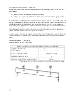
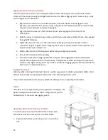
the enclosure) until they stop. DO NOT PULL OUT THE PIN GRIPS AS THEY ARE SUSPENDING
THE BOTTOM MODULE FROM THE ONE ABOVE IT. Lock the Rigging Latches in the retracted
position by rotating the Latch Grips inwards (towards each other) 90 degrees. The Latch Grip
handles will now be oriented horizontally (pointing inwards).
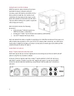
(Fig. 1, upper module)
3.
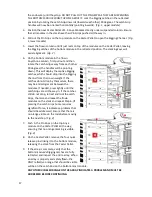
Position the next Caster Pallet of 1-4 Anya Modules directly under suspended column. Ensure
that all modules in the stack have their Pin Grips pushed all the way in.
4.
Pull out the Pin Grips on the top module on the Caster Pallet to open the Rigging Channel.
(Fig.
1, lower module)
5.
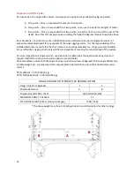
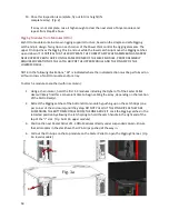
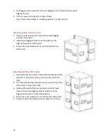
Lower the flown column until it just rests on top of the modules on the Caster Pallet, leaving
the Rigging Latches of the bottom module in the retracted position. The stacking keys will
assist alignment.
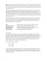
(Fig. 2)
6.
On the bottom module in the flown
Anya/Anna column, first pull out and then
rotate the Latch Grips away from each other
90 degrees (the handles will be pointing
down). This will deploy the captive Rigging
Latches, which should drop into the Rigging
Channel from their own weight. If the
Latches do not drop by themselves, there
may be a misalignment between the
modules. If needed, press lightly until the
Latch Grips are all the way in. If the Latches
still do not drop, retract and lock the Latch
Grips, the raise and reseat the flown
modules on the stack and repeat Step 6. (If
pressing the Latch Grips home requires
significant force, it indicates a problem that
should be addressed.) Ensure that there is
no orange visible on the rods before moving
to the next step.
(Fig. 2)
7.
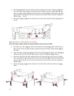
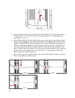
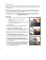
Push in the Pin Grips on the top Anya
module on the Caster Pallet all the way,
ensuring that no orange marking is visible.
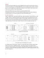
(Fig. 3)
8.
On the Caster Pallet, remove the four quick-
release pins linking it to the bottom module,
releasing the stack from the Caster Pallet.
9.
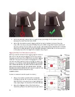
If the array is complete, verify that the
bottom module’s Rigging Latches are fully
retracted and inspect the entire array. When
an array is properly and safely flown, the
ONLY reflective orange that should be visible
will be on the Latch Rod on the bottom-most module.
ANY OTHER VISIBLE ORANGE ON THE ARRAY INDICATES A PROBLEM AND MUST BE
ADDRESSED BEFORE CONTINUING
.
Summary of Contents for ADAPTive systems
Page 1: ...Accessory Rigging Guide...

