background image

Warnings  

WARNING:

 Suspending anything, especially overhead of people, should be done with extreme caution. 

Always engage the services of a certified professional who is qualified to determine the requirements 
for and to implement overhead rigging. Only persons with the knowledge of proper hardware and safe 
rigging techniques should attempt to suspend ADAPTive module columns overhead. Failure to follow 
these precautions may result in damage, injury, or death. 

DANGER: 

When suspending or stacking ADAPTive modules, avoid placing any parts of the body 

between the enclosures or between an enclosure and the Flybar. Always use the integral handles to lift 
or position enclosures. Failure to follow this precaution may result in damage, injury, or death. 

CAUTION:

 The physical size of each ADAPTive product means that more than one person will be 

required to lift and carry it. However, always use proper lifting techniques to avoid injury. Use good 
judgment to determine if you need lifting assistance such as another person, a back support belt, or 
mechanical assistance. 

IMPORTANT RIGGING WARNING:

 Each captive Rigging Pin is used to attach modules together within 

an internal rigging substructure integral to the enclosures. There is no option to splay each module and 
the modules are only designed to be flown in a straight vertical orientation. Use the correct holes on 
the Flybar as determined by EAW Resolution 2, based on rigging conditions and weight restrictions. 

Ground Stacking  

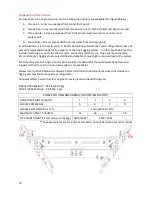
ADAPTive columns may be ground-stacked. Normally, a ground-stacked main column is used where 
suspension is not possible, too difficult, or too time-consuming. The ADAPTive Caster Pallets may be 
used to stack up to four modules. Ensure that the casters are chocked and that the ground or stage is 
plumb and level. 

WARNING:

 Ground-stacked columns, especially the maximum recommended columns requires 

assembly by personnel qualified to ensure adequate stability from tip over for the particular 
application. 

Flying 

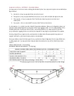
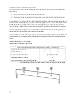
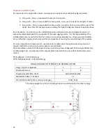
Suspension Load Rating – Working Load Limits (WLL) . 

CAUTION:

 Different combinations of modules and Flybar mounting locations allow for a variety of 

hanging positions which creates unique loading of stresses on structural members in any given column. 
Always consult Resolution for specific WLL information for any given column configuration. 

WARNING:

 It is the responsibility of the user to ensure the attachment to the Flybar, the rigging 

method, and attachment to structure are inspected by a certified professional who is qualified to 
determine the requirements for and implement overhead rigging. 

Summary of Contents for ADAPTive systems

Page 1: ...Accessory Rigging Guide...

Page 2: ...rd Flybar 11 Suspension of Anna OPTION 2 Flybar Lite 12 Suspension of Otto Flybar 13 Rigging Modules to Flybar Single column Anya 14 Rigging Modules to Flybar Single column Anna 14 Rigging Modules to...

Page 3: ...2 Anya Caster Pallet 25 Anna Caster Pallet 26 Otto Caster Pallet 27 Service Inspection Maintenance 28 General Service 28 Contacting EAW 28 Operating Questions 28 Service Information 28...

Page 4: ...ach fully loaded Distro Rack is capable of supplying up to 12 ADAPTive modules with full power and with complete data redundancy If the user elects not to employ data redundancy each Distro Rack could...

Page 5: ...onous output To ensure correct cabling ADAPTive Systems include a cable package based around 6 module fan out looms of customized lengths as well as extenders This system supports a variety of array l...

Page 6: ...r provided solution meet these specifications Cable Ethernet CAT5e UTP or better 300 feet 91 meters maximum etherCON Connector RJ45 with or without Neutrik NE8MC cable carrier Multi Pin Connector Link...

Page 7: ...tories power distribution unit s or PDU s One PDU is capable of powering six 6 modules as well as two data switches Up to two PDUs may be mounted in a Distro Rack but each PDU must be powered directly...

Page 8: ...perate on voltages ranging from 90 to 265V AC 50 60 Hz No module setting changes are necessary to switch between regional voltage ranges 120 208 220 etc As with data ADAPTive systems include pre defin...

Page 9: ...oduct Electrical Warnings AC MAINS SUPPLY WARNING Read all instruction and cautionary notes concerning electrical power in the EAW Loudspeaker Owner s Manual AC Mains Cable The AC mains cables supplie...

Page 10: ...integral to the enclosures There is no option to splay each module and the modules are only designed to be flown in a straight vertical orientation Use the correct holes on the Flybar as determined b...

Page 11: ...i e slings spansets shackles etc and facility s rigging structure is certified and capable of meeting the required load of the system For arrays larger than a single column use Resolution to determine...

Page 12: ...s connecting members i e slings spansets shackles etc and facility s rigging structure is certified and capable of meeting the required load of the system For arrays larger than a single column use Re...

Page 13: ...s rigging structure is certified and capable of meeting the required load of the system For arrays larger than a single column use Resolution to determine the appropriate hang style and support method...

Page 14: ...he chain motors connecting members i e slings spansets shackles etc and facility s rigging structure is certified and capable of meeting the required load of the system For arrays larger than a single...

Page 15: ...ou do not see the orange reflective tape Any visible orange indicates that the pins are not fully engaged Pull the Pin Grip all the way out then firmly push the Pin Grip in until you feel a positive s...

Page 16: ...s already on top of stacks 1 The Flybar has built in Rigging Latches that will slide into the 4 Rigging Channels of the top Otto module On the top Otto module pull back on the 4 Pin Grips to open the...

Page 17: ...on the simple and safe Rigging Latch and pin design Two grips on each side of the Power Plant control the rigging elements The upper Pin Grip drives the Rigging Pins in and out while the lower Latch...

Page 18: ...he captive Rigging Latches which should drop into the Rigging Channel from their own weight If the Latches do not drop by themselves there may be a misalignment between the modules If needed press lig...

Page 19: ...where the indicated action must be performed on all four corners of an Otto module and or array To attach a module to another within a column 1 Using a chain motor hoist the first 1 3 modules includin...

Page 20: ...themselves there may be a misalignment between the modules If needed press lightly until the Latch Grips are all the way down If the Latches still do not drop retract and lock the Latch Grips the rai...

Page 21: ...y When an array is properly and safely flown the ONLY orange that should be visible will be on the Latches of on the bottom most module ANY OTHER VISIBLE ORANGE ON THE ARRAY INDICATES A PROBLEM AND MU...

Page 22: ...s needed to align the columns Once the columns are at the same height align the two columns such that the tabs of one Flybar engage with the slots of the other Flybar 4 Slide the columns relative to e...

Page 23: ...uick release hub 5 Attach chain motors to the Flybars as defined by your Resolution model 6 Fly out the first stack of Otto modules 7 Proceed as indicated in Rigging Modules to Flybar and Rigging Modu...

Page 24: ...Distro Rack 3 Re pin the quick release pins to lock the Flybar to the Distro Rack Attaching Multiple Distro Racks 1 Once detached from Caster Pallet lift Distro Rack by either physical or mechanical...

Page 25: ...ommended that you do not attempt this installation while the system is suspended in air 1 Inventory of your kit Your kit will include 1 Black 25mm Screw Lock Carabiner 2 Locate Carabiner Mounting Poin...

Page 26: ...et so that the stack pads line up with the bottom module 2 Release the 4 quick release pins from the Caster Pallets Rigging Channels 3 Pull and turn the Latch Grips to release the Rigging Latches from...

Page 27: ...Anna module line up with the recesses in the pallet 2 Release the 2 quick release pins from the Caster Pallets Rigging Brackets 3 Pull and turn over to left the two 2 Latch Grips to release the Riggi...

Page 28: ...he Otto module line up with the recesses in the pallet 2 Release the 4 quick release pins from the Caster Pallets Rigging Brackets 3 Push over to left the four 4 Latch Grips to release the Rigging Lat...

Page 29: ...ing EAW We have attempted to make this manual and the Resolution Help File as thorough as possible However feel free to contact us with any further questions or comments for topics not covered Operati...

Page 30: ...hts reserved Products are not drawn to scale All terms conditions and specifications subject to change without notice RD3026 A Eastern Acoustic Works One Main Street Whitinsville MA 01588 USA tel 800...

Reviews: