background image

6

Eaton Remote Monitoring Device (RMD) Installation and Operation Manual P-164000516—Rev 02

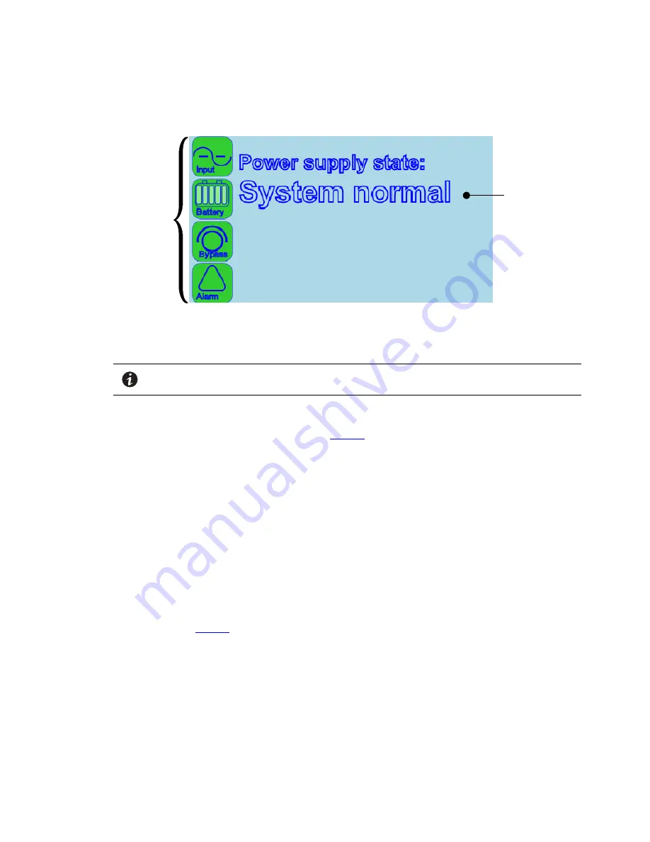
Figure 5. Display Screen Sections

Information
Area

Status

Indicator

Icons

P

Poow

weerriinngg tthhee R

RM

MD

D

NOTE

The PXG card must be setup and running in the UPS before starting the RMD. If
powered up together the RMP may not establish communication.

To turn the RMD on press and hold the power pushbutton on the front of the RMD (see ) for three seconds.
The RMD should start with the Eaton logo being displayed. Then the power pushbutton on the front of the
RMD will illuminate green and the screen shown in

Figure 5

should be displayed. If the display does not start,

let the battery charge for 30 minuets.

To turn the RMD off press and hold the power pushbutton on the front of the RMD for approximately
11 seconds.

If a white screen is displayed on the RMD after the UPS is turned on, press and hold the power pushbutton on
the front of the RMD for 15 seconds (while the power cable is plug in) and the RMD will subsequently establish
communication with the PXG card.

S

Siilleenncciinngg tthhee A

Auuddiibbllee A

Allaarrm

m

To silence the audible alarm, press the power button momentarily.

S

Syysstteem

m EEvveennttss

The following paragraphs describe the typical information that can be displayed on the RMD screen.

Communications Fault Screen

– If a communication issue occurs between the RMD and the UPS the

message shown in

Figure 6

will be displayed. Check the state of the Ethernet 10/100 (RJ45) connection

examine both LEDs on the RMD. One represents Activity (ACT) and the other represents the speed (10/100) at
which that activity is occurring. Specifically, network communication is occurring when the green ACT indicator
is blinking. If this indicator is not illuminated then there is no network activity. The other LED represents the
speed of the network connection. If this indicator is illuminated yellow then that indicates a valid 100 Mb
connection. If this indicator is not illuminated it indicates a valid 10 Mb connection as long as the corresponding
ACT is blinking green.

If the Activity LED on the RMD is not blinking green, check that the network cable is the correct type and
securely connected to the Ethernet 10/100 port for both the PXG card and the RMD.

Operation

Summary of Contents for Remote Monitoring Device

Page 1: ...p n P 164000516 Revision 02 Installation and Operation Manual Eaton Remote Monitoring Device...

Page 2: ...rved No part of this document may be reproduced in any way without the express written approval of Eaton IMPORTANT SAFETY INSTRUCTIONS SAVE THESE INSTRUCTIONS This manual contains important instructio...

Page 3: ...e em mo ot te e M Mo on niit to or riin ng g D De ev viic ce e 1 1 Introduction 1 Installation 2 Network Card Installation 2 Network Card Configuration 3 RMD Installation 3 Operation 5 RMD Components...

Page 4: ...iv Eaton Remote Monitoring Device RMD Installation and Operation Manual P 164000516 Rev 02 Table of Contents...

Page 5: ...UPS from virtually any location within the facility up to 300 feet from the UPS It will display the general state of the UPS and key metrics like battery charge and available runtime when on battery...

Page 6: ...PXG card or Power Xpert Gateway Xslot PXGX card must be installed in the UPS to use the RMD Install the PXG card into the UPS Minislot or the PXGX card into the UPS Xslot Refer to the applicable Eato...

Page 7: ...RJ45 Ethernet connector on the RMD see Figure 4 3 Connect the Cat5 cable to the RJ45 Ethernet connector on the PXG card Refer to the applicable Eaton UPS Installation and Operation manual for the UPS...

Page 8: ...he PXG card has illuminated connect the charger cord micro USB connector to the micro USB connector on the RMD see Figure 4 Connect the transformer side of the charger cord to a 120 Vac service outlet...

Page 9: ...Figure 5 shows the display screen sections Input This icon shows the state of the incoming power It is green if the power is available and good If it turns yellow the voltage or frequency of the elec...

Page 10: ...th the PXG card S Siille en nc ciin ng g t th he e A Au ud diib blle e A Alla ar rm m To silence the audible alarm press the power button momentarily S Sy ys st te em m E Ev ve en nt ts s The followin...

Page 11: ...seconds 3 Remove and re seat the PXG card within the mini slot and waiting approximately two minutes until the Status indicator is illuminated 4 Once illuminated turn the RMD back on by re inserting t...

Page 12: ...a will display the remaining backup time in minutes and seconds Both the Input and Battery icons are illuminated yellow due to loss of input power while the UPS is on battery Figure 8 On Battery Scree...

Page 13: ...indicates the UPS has an active alarm and requires immediate attention If this occurs check the state of the UPS and if necessary contact service as the UPS may not be able to provide backup power All...

Page 14: ...y of the following Scheduling initial startup Regional locations and telephone numbers A question about any of the information in this manual A question this manual does not answer Please call the Hel...

Page 15: ...Eaton Remote Monitoring Device RMD Installation and Operation Manual P 164000516 Rev 02 11 Equipment Registration...

Page 16: ...P 16400051602 P 164000516 02...

Reviews: