Chapter 6—Installation Requirements
DG1 Series VFD
MN040002EN—March 2014
www.eaton.com
39
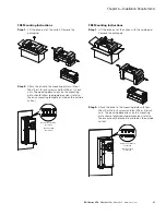
Ground Connection
The ground connection is connected directly with the cable
clamp plates.
The shielded cables between the frequency inverter and the
motor should be as short as possible. Connect the shielding
on both ends and over a large surface area with protective
ground PES (Protective Earth Shielding). You can connect the
shielding of the motor cable directly to the cable clamp plate
(360 degrees coverage) with the protective ground.
The frequency inverter must always be connected to the
ground potential via a grounding cable (PE).
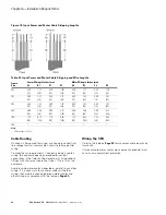
Figure 25. Grounding
CAUTION
Before connecting the AC drive to mains make sure that the
EMC protection class settings of the drive are appropriately
made.
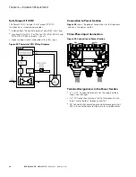
Note:
After having performed the change write “EMC level
modified” on the sticker included in the DG1 delivery
(see
Figure 26
) and note the date. Unless already
done, attach the sticker close to the name plate of the
AC drive.
Product Modified Sticker
Figure 26. Product Modified Sticker
Checking the Cable and Motor Insulation
1.
Check the motor cable insulation as follows:
●
Disconnect the motor cable from terminals U, V and
W of the DG1 Series drive and from the motor
●
Measure the insulation resistance of the motor cable
between each phase conductor as well as between
each phase conductor and the protective ground
conductor
●
The insulation resistance must be >1M ohm
2.
Check the input power cable insulation as follows:
●
Disconnect the input power cable from terminals
L1/N, L2/N and L3 of the DG1 Series drive and from
the utility line feeder
●
Measure the insulation resistance of the input power
cable between each phase conductor as well as
between each phase conductor and the protective
ground conductor
●
The insulation resistance must be >1M ohm
3.
Check the motor insulation as follows:
●
Disconnect the motor cable from the motor and open
any bridging connections in the motor connection box
●
Measure the insulation resistance of each motor
winding. The measurement voltage must equal at
least the motor nominal voltage but not exceed 1000V
●
The insulation resistance must be >1M ohm
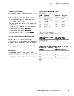
15
25
(FR1–FR4)
No. 2 Phillips
(FR5)
No. 3 Phillips
(FR1–FR3)
PE
(FR4, FR5)
(FR1–FR3)
M4, 10 in-lb (1.1 Nm)
(FR4)
M4, 14 in-lb (1.6 Nm)
(FR5)
M6, 35 in-lb (4.0 Nm)
Summary of Contents for PowerXL DG1-32011FB-C21C
Page 1: ...PowerXL DG1 Series VFD Installation Manual Effective March 2014 New Information ...
Page 2: ......
Page 83: ......


