49
Instructions for installation and use of low temperature kits
SPLIT RACK AIR CONDITIONER USER MANUAL
UM.ICUBE2.0-SRAC.SG.0822 August 2022 www.eaton.com
terminal of the outdoor unit by the grounding terminal of the cryogenic assembly.
ote:
N
Brown wire and blue wire are two-core low-temperature resistant cables with low temperature compo-
nents, with a length of 5 meters.
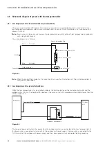
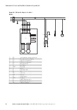
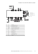
The wiring diagram is as follows:
Cryogenic components
Temperature control switch
Outdoor unit
Brown Cables of the unit
Blue Cables of the unit
Yellowish green
3
N(1)
2
Grounding
terminal
Grounding terminal
Outdoor unit
Wire terminal
Power
connection
Electric heating sheet
Low temperature kits
Figure 6.5
6.5 Pipe diameter, vacuum, refrigerant filling and addition of frozen oil
6.5.1 Connecting pipe diameter of low temperature kits
The inlet pipe and outlet pipe of the low temperature kits are connected by 3/8 inch globe valve, and the actual
on- site connection pipeline refers to the requirements of the nozzle in the installation instructions. The kit is
connected with the liquid pipes of the indoor unit and the outdoor unit respectively, When the diameter of the
liquid pipe of the indoor and outdoor unit of the air conditioner is different from that of the globe valve, it is
necessary to enlarge or shrink the liquid pipe of the internal and external machine respectively and then weld one
end of the liquid pipe of the low temperature kits, and the other end of the liquid pipe of the low temperature kit
is threaded to its own globe valve through the trumpet thread.
Safety valve
One-way valve
Liquid reservoir
Outlet pipe
φ
9.52
(with globe valve)
Intake pipe
φ
9.52
(with globe valve)
Figure 6.6
(There may be design changes in the specific pipe diameters and connection types. This is subject to the actual
items provided.)


