background image

46

Manual operator (optional kits)

SPLIT RACK AIR CONDITIONER USER MANUAL

   UM.ICUBE2.0-SRAC.SG.0822   August 2022   www.eaton.com

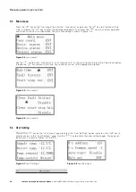
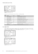
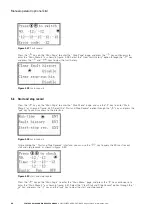
Figure 5.35

 rotation setting 2

H-temp.

High temperature

H-humi.

High humidity

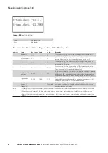
The parameters of the rotation setting are shown in the following table:

Serial 

number

Name

Set range

Unit

Default 

value

Remarks

1

Number of 

rotation units

1~12

3

The number of rotation units is set according to the actual number of 

units. The default is 3 units.

2

Rotation address 0~11

0

If the address is 0, it is the host; the address is 1~11 slave (it is 

recommended to set the most commonly used one as the host)

3

Rotation time

0~99

Time

8

The timing rotation time is set according to the actual need; when the 

rotation time is 0, it is the rotation test time, and the corresponding 

rotation time is 5 minutes.

4

Rotation

Disable /

Forbidd

If you choose N+1, there is one setting N+1/N+2 en backup unit in the 

system, and if you select N+2, there are two standby units in the system. 

Stand-alone applications are disabled by default.

5

High temperature 

deviation

0~20.0

°C

5.0

In the rotation operation, the return air temperature > the set temperature 

+ high temperature deviation, turn on the standby machine; the return 

difference is 3 ℃ to automatically reset and close the standby machine 

(the return difference refers to the standby start-up temperature point-3)

6

High humidity 

deviation

0~20.0

%RH

10.0

Turn on the standby machine when return air humidity > set hu 

high humidity deviation during rotation operation; the return error is 5% 

automatically reset and turn off the standby machine

7

Operation 

function of 

standby fan

-

-

Prohibited

If allowed, the fan in the standby air conditioner will run when it is 

on standby; the default is disabled, and the fan will not run when the 

standby machine is on standby.

Note

1)  Except for the second [rotation address], which is different from the master / slave, the above parameters should be set in the same 

way as the master / slave.

2)  When the air conditioner fails, the main and standby units are automatically switched by the air conditioner logic without manual 

intervention.

3)  After setting the group control parameters, restart the power off of the air conditioner to ensure that the modified parameters take 

effect.

Summary of Contents for MDC

Page 1: ...Eaton Micro Data Center Split rack air conditioner User manual ...

Page 2: ...ESS FOR A PARTICULAR PURPOSE OR MERCHANTABILITY OTHER THAN THOSE SPECIFICALLY SET OUT IN ANY EXISTING CONTRACT BETWEEN THE PARTIES ANY SUCH CONTRACT STATES THE ENTIRE OBLIGATION OF EATON THE CONTENTS OF THIS DOCUMENT SHALL NOT BECOME PART OF OR MODIFY ANY CONTRACT BETWEEN THE PARTIES In no event will Eaton be responsible to the purchaser or user in contract in tort including negligence strict liab...

Page 3: ...onnection 15 2 8 Installation of drain pipe 19 2 9 Vacuum and refill frozen oil 20 2 10 Refrigerant charging 21 2 11 Electrical wiring 22 3 Unit operation 28 3 1 Common tools 28 3 2 Power supply and instrument inspection 28 3 3 Refrigeration system inspection 28 3 4 Unit commissioning 28 3 5 Unit shutdown 29 3 6 Daily operation inspection of unit 29 3 7 Test record and form 29 4 Unit maintenance 3...

Page 4: ...ation 47 6 2 Dimension of low temperature kits 47 6 3 Schematic diagram for internal structure of low temperature kits 47 6 4 Schematic diagram of system with low temperature kits 48 6 4 1 Low temperature kits are installed indoors recommended 48 6 4 2 Low temperature kits are installed outdoors 48 6 5 Pipe diameter vacuum refrigerant filling and addition of frozen oil 49 6 5 1 Connecting pipe dia...

Page 5: ... for relevant information Safety warning I Safe Handling The handling of the unit shall follow the relevant local laws and regulations and strictly abide by the following provisions The equipment must be carried by trained personnel When handling it is strictly forbidden to use the parts as the pressure point to prevent damage to the parts If you accidentally drop it in the process of handling ple...

Page 6: ...nt temperature 18 45 maximum humidity is 80 RH and there is no condensation The air conditioner should not run beyond the above range for a long time otherwise it may damage the air conditioner or cause safety accidents VI Maintenance and repair The maintenance and repair of the unit must be carried out under the guidance of qualified personnel The electrical appliances of the unit are dangerous D...

Page 7: ...ment The air conditioner is embedded into the rack It is efficient energy saving safe and reliable In addtion it comes with intelligent management and a compact structure All of which will help meet the cooling needs of the rack 1 2 Unit outline drawing 1 Outline drawing of E04SE unit The standard size of E04S is 217 mm 440 mm 760 mm height width depth Figure 1 1 2 Outline drawing of E08SE unit Th...

Page 8: ...UBE2 0 SRAC SG 0822 August 2022 www eaton com 3 Exterior drawing of EW06E air cooled outdoor unit Figure 1 3 4 Exterior drawing of EW10E air cooled outdoor unit Figure 1 4 The outline of the unit may vary depending on the machine model and requirements selected by the user ...

Page 9: ...small computer room E EATON 2 Cooling capacity 04 08 Cooling capacity level such as 04 for 4 KW 3 Air conditioning styles S split type 4 In China or oversea model E E oversea model Table 2 Description of outdoor unit model Sequence 1 2 3 Codes EW 06 E Sequence Meanings Codes Description 1 Series name EW E EATON brand special outdoor air conditioner for computer room W outdoor unit 2 Heat exchange ...

Page 10: ...ponsibility for the correct custody and installation of the unit NOTICE If the unit needs to be stored before installation the following preventive measures should be taken Ensure that all openings such as water pipes and copper pipes have protective covers Store the unit in a dry and vibration free place with less personnel activity Rain proof measures should be taken when it is stored outdoors D...

Page 11: ... space around the installation location to prepare for the operation and maintenance of the air conditioner indoor unit The recommended installation space dimensions for server cabinets with rack air conditioner are shown in the following figure 2 2 Figure 2 2 Outdoor unit The installation space requirements for outdoor units are shown in the following The distance from the wall is greater than 30...

Page 12: ...he gas circuit and liquid circuit globe valves of the indoor unit with 5mm inner hexagon spanner respectively and connect the pressure gauge to exhaust on the gas path needle valve and the liquid path needle valve respectively Please check the vacuum section 2 8 for specific valve location The complete nitrogen release operation must be carried out after the copper pipe connection of the indoor un...

Page 13: ...rformance needs to be re calibrated after 6 months 2 6 Unit installation NOTES The impact on the appearance of the building should be taken into account in the installation of outdoor units The installation location should be chosen as far as possible where the pipeline is short the bend is less and the height difference is small When the outdoor unit is not on the ground or the roof plane but is ...

Page 14: ...12mm Impervious grade RMA A Vacuum replenish charge refrigerant Check system pressure Refrigerant DuPont SUVA R410A is recommended Charge replenish refrigerant Electronic weighing Resolution 5g Accuracy 5 Built in solenoid valve automatic quantitative injection Charge replenish cold refrigerant weighing Vacuum pump R410A special vacuum pump with solenoid check valve Absolute pressure of 12Pa Vacuu...

Page 15: ...ion Copper tube processing For expanding the trumpet mouth used to connect with the globe valve Copper tube expander copper pipe connection Tube expansion for cup mouth For on line tube flaring for the connection between on line pipes Live wrench It is used to fasten the connection between the napkin cap and the globe valve Torque wrench Torque range 20 110 N M It is used to fasten the connection ...

Page 16: ... terminals Press OT segments tube terminals etc 2 6 2 Installation material preparation Serial number Specifications Remarks The indoor and outdoor units are connected with copper pipes and related thermal insulation Please refer to 2 6 Pipeline connection to select the relevant specifications It is related to the type of the unit and the length of the pipe Gravity drain pipe Hard PVC pipe outside...

Page 17: ...e same Figure 2 7 1 First fix the left bracket with one M10X100 or more bigger expansion screw 2 After determining the level with a horizontal ruler put other bolts on the other side 3 Then put the outdoor unit on the installed bracket 4 Tighten all the M8X30 anchor screws Note N 1 Install the bracket with crossbeam produced by the manufacturer 2 When assembling the bracket the bolts should be pie...

Page 18: ...ess it with a fixed wire clamp 3 Tidy up the wires put the excess wires into the outdoor unit cover the handle and tighten the screws 4 Coil the excess pipeline behind the external unit arrange the direction of the pipeline to ensure that the connecting pipe is horizontal and vertical Do not touch the wall or the bracket etc 2 6 4 Indoor unit installation The indoor unit is installed at the bottom...

Page 19: ... front air supply is adopted E04SE E08SE The effect after installation is as follows The effect after installation is as follows Sealing plate Sealing plate Figure 2 13 Figure 2 14 Note N The sealing plate is been installed in the factory 2 7 Pipeline connection Pipeline cleaning Ensure that the pipeline is clean and free of rust oxide scale sand oil etc During the installation and maintenance of ...

Page 20: ...ter mm Equivalent length m Copper pipe diameter mm 45 Elbow 90 Elbow 180 Elbow 15 88 0 15 0 25 0 5 12 7 0 14 0 25 0 5 9 52 0 10 0 20 0 34 6 0 06 0 12 0 24 If the connecting pipeline length between indoor and external units is more than 10m it is necessary to increase the connecting pipe diameter appropriately in order to reduce the system flow resistance and the recommended size of the pipeline is...

Page 21: ...Floor The insulation layer under the floor Condensate drain pipe Movable floor Up to 20 0m Figure 2 15 a Installation schematic diagram for that outdoor unit is higher than indoor unit Pneumatic tube inclination Liquid tube inclination Cabinet Indoor unit Up to 5 0m The insulation layer under the floor Seal Outdoor unit Floor Condensate drain pipe Movable floor Figure 2 16 b Installation schematic...

Page 22: ...pper pipe when passing through the wall After finishing it is necessary to charge dry nitrogen test leakage and vacuum Eaton Corporation is not responsible for the damage to the unit caused by incorrect operation procedures outlined in this manual 1 Tool preparation All tools spare parts and materials must be ready such as inner hexagon spanner impact drill vacuum pump nitrogen cylinder piping too...

Page 23: ... the vacuum procedure 7 Thermal insulation Connect the copper pipe and wrap the insulation layer The wall thickness of the heat preservation pipe is 9 25 mm and the material is rubber plastic foam 8 Connecting cable Please select the cable according to the electrical connection requirements and properly wrap and secure the cable with plastic tape 9 Open the gas and liquid globe valves of the outdo...

Page 24: ...should be in the negative area and the sound of the vacuum pump is relatively low At this time the vacuum pressure gauge can be closed and opened several times and there should be no obvious change in the pointer position of the pressure gauge and the sound of the vacuum pump before and after closing otherwise the refrigeration system may be poorly sealed Step 4 After confirming that there is no l...

Page 25: ...ve can be connected by pressure hose Refueling position Add frozen oil at the air path needle valve of the indoor unit Refrigerant addition refers to the refrigerant dose that exceeds the standard charge and it is generally necessary to add refrigerant when it exceeds the standard connecting tube It is necessary to increase the amount of frozen oil for cryogenic assemblies Please refer to the inst...

Page 26: ...at the power supply is consistent with the nameplate requirements In order to avoid corrosion and overheating at the terminal connection all power supply lines are required to be copper wires The specification of the power cord connected to the electric control box shall be selected according to the maximum operating current on the nameplate The total power supply must have a certain margin and th...

Page 27: ...he power supply of the outdoor unit is provided by the indoor unit and the cable is shown in the figure 2 22 Outdoor side wiring Indoor side wiring Power cord Communication line Tubular terminal E2512 is recommended OT terminal M4 is Recommended Tubular Terminal E2512 is recommended Figure 2 22 Wiring instructions for power terminal of the unit The connection method of the power terminal is as fol...

Page 28: ...e selection principles for installing circuit breakers in air conditioners are as follows 1 Generally choose plastic shell type circuit breaker 2 The rated voltage of the circuit breaker is not lower than the rated voltage of the circuit the rated current of the circuit breaker is not lower than the calculated current passing through it 3 The circuit breakers of air conditioners should be installe...

Page 29: ...le 2 Model Maximum operating current Recommended specifications for power cords and communication lines Communication line specification E08SE 15 7A including outdoor unit 3 2 5mm2 EW10E 13 8 A 3 2 5 mm2 2 1 5 mm2 Communication connection There are 4 communication interfaces in the form of network interface behind the rack precision air conditioner as shown in the following figure 2 25 Schematic d...

Page 30: ...perature and humidity data fault information and other contents to achieve temperature setting unit start and stop and other operations PORT1 PORT2 PORT1 PORT2 PORT1 PORT2 PORT1 PORT2 Unit 1 Unit 2 Unit 3 Unit N Host computer 1 8 RS485 RS485 Figure 2 27 Wiring diagram for host computer communication PLAN Group control communication interface supports MODBUS RTU communication protocol The group con...

Page 31: ...e power input of all indoor units is single phase three wire L N PE please pay close attention to the installation The cable connecting the indoor and outdoor units is self equipped by the user The supply voltage must be in the normal range 187 253V The original circuit in the unit is not allowed to be changed under any circumstances Do not connect the wiring of L and N upside down All terminals m...

Page 32: ...king effectively Carefully check all electrical lines with a multimeter to check that the wiring is properly installed measure with megohmmeters to make sure there is no shell short circuit check that the grounding wire is properly installed and that the insulation resistance to the ground is greater than 2 MΩ check that the power cord meets the capacity requirements Check whether the circuit brea...

Page 33: ...rd Indoor unit model See nameplate Outdoor unit model See nameplate Indoor unit number See nameplate Outdoor unit number See nameplate SN code See the rear of the unit SN code See below the nameplate Indoor ambient temperature during test run General 24 c 30 c Total current of outdoor unit Less than the maximum current of the nameplate Indoor ambient humidity during test run Generally 40 60 conden...

Page 34: ... sensor 2 Regularly check that the operation of the compressor is the same as sound and vibration 3 The air filter is recommended to be inspected and cleaned once every 3 months If it is damaged please replace it 4 For the first time after a long term shutdown the power switch is turned on at least 24 hours in advance and the dust filter and water plate are cleaned 5 The electric control box is pu...

Page 35: ... The compressor started but soon stopped because of thermal protection Too much or too little refrigerant Leak detection charge according to the correct refrigerant charge There is air or non condensable gas in the refrigeration circuit Re vacuum and charge refrigerant Compressor failure Find out the cause and replace the compressor The voltage is too high or too low Find out the cause and stabili...

Page 36: ... setting operation can be entered without a password which is sufficient for the daily use of users 2 For engineers or service after sales personnel press ENT and SET at the same time on the main page to enter the password login page enter the correct password 889900 to enter the relevant menu page this operation suggestion is only available to engineers or service personnel 3 ALARM 1 On any page ...

Page 37: ...ctual temperature the current return air temperature is displayed when Temperature Control is set to return air and the current supply air temperature is displayed when Temperature Control is set to supply air Line 2 the current return air humidity is displayed Line 3 displays the current status of the unit shutdown running or downtime no fault or fault Line 4 displays the current system time 5 4 ...

Page 38: ...own in figure 5 4 Figure 5 4 main menu 1 Use the key to enter main menu 2 and main menu 3 as shown in figures 5 5 and 5 6 Select each option through the key and press the key to confirm access to the appropriate interface Figure 5 5 main menu 2 Figure 5 6 main menu 3 5 6 User Setting Press the key on the main menu page to select the User Settings option and press the key to confirm access to the U...

Page 39: ...ter communication address 1 255 1 The communication address of the host computer is set there can only be a maximum of 32 units on a bus Power off restart is required after parameter modification 6 Host computer communication rate 1 3 2 1 4800 2 9 600 3 19 200 Power off restart is required after parameter modification 7 Incoming call self starting Disable enable Enable Enable set up of incoming ca...

Page 40: ...ure C Suction temperature of the compressor of the unit 7 Condensation pressure bar The condensing pressure of the compressor of the unit 8 Low pressure bar The low pressure of the compressor of the unit 9 Outdoor ambient temperature C The ambient temperature of the outdoor unit 10 Compressor IPM module temperature C The temperature of the outdoor inverter IPM module displays 60 C when the module ...

Page 41: ...AIR CONDITIONER USER MANUAL UM ICUBE2 0 SRAC SG 0822 August 2022 www eaton com Figure 5 14 device status 3 Figure 5 15 device status 4 Figure 5 16 device status 5 Figure 5 17 device status 6 Figure 5 18 device status 7 Figure 5 19 device status 8 ...

Page 42: ...rking state of electric heating Stop run 12 Working state of internal fan Stop run 13 Working state of external fan Stop run 14 Speed of 1 internal fan 0 9999 RPM 1 Actual speed of internal fan 15 Speed of 2 internal fan 0 9999 RPM 2 The actual speed of the internal fan is displayed as 0 when the number of indoor fans 1 16 Indoor fan speed 0 100 Control speed of internal fan 17 Speed of outdoor fa...

Page 43: ...put point 3 2 indoor fan failure Close break Status of the current input point 4 High level switch Close break Status of the current input point 5 Electric heating protection Close break Status of the current input point 6 Flooding fault Close break Status of the current input point 5 6 4 Unit running time On the Main Menu page press the key to enter the Main Menu 2 page press the key to select th...

Page 44: ...r failure Missing or short circuit of return air humidity sensor Check the return air temperature and humidity sensor and its wiring and reset automatically after troubleshooting 6 Maintenance failure of indoor fan The cumulative running time of the part exceeds the set limit default 10000 hours Reset manually after zero clearing 7 Maintenance failure of compressor The cumulative running time of t...

Page 45: ...aust high temperature alarm The exhaust temperature is too high Check whether the condensing fan is running check whether the condenser is dirty and clogged and check whether the undercooling is too high Automatically reset after troubleshooting 32 High voltage switch action H2 High voltage switch action of outdoor unit Check whether the condensing fan is running check whether the condenser is dir...

Page 46: ... internal and external computers Check the wiring of internal and external machines Automatically reset after troubleshooting 73 Power loss alarm The power supply is lost and then restored while the unit is in operation It will be released automatically after 10 seconds 74 Shut off failure of globe valve The change of low pressure pressure during start up of the unit is too small Please make sure ...

Page 47: ... external fault is eliminated some of the faults will recover automatically When the fault needs to be reset manually press the key on the Main Page to reset the fault manually 5 7 4 Fault record Press the key on the Main Page to enter the Main Page page and enter Main Page 2 through the key as shown in figure 5 26 Use the key to select the Fault History option and press the key to confirm access ...

Page 48: ...ge to enter the Main Menu page and use the key to enter Main Menu 2 as shown in figure 5 29 Select the Start and Stop Record option through the key and press the key to confirm access to the interface Figure 5 29 main menu 2 After entering the Start and Stop Records interface you can use the key to query the 50 most recent start and stop records as shown in figure 5 30 Figure 5 30 start and stop r...

Page 49: ...face and enter the user Settings 2 interface through the key as shown in figure 5 33 Figure 5 33 User Settings 2 H temp High temperature H humi High humidity Select the Rotation Setting option through the key and press the key to confirm entry as shown in figures 5 34 and 5 35 Press the key to enter the setting state and select the first parameter Continue to press the key to select other paramete...

Page 50: ...ault 5 High temperature deviation 0 20 0 C 5 0 In the rotation operation the return air temperature the set temperature high temperature deviation turn on the standby machine the return difference is 3 to automatically reset and close the standby machine the return difference refers to the standby start up temperature point 3 6 High humidity deviation 0 20 0 RH 10 0 Turn on the standby machine whe...

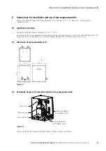
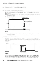
Page 51: ...le for outdoor ambient temperature 40 45 low temperature kits are developed and designed to meet the requirements in northern extremely cold areas The purpose is to ensure the normal start up and reliable operation of air conditioning units in winter 6 2 Dimension of low temperature kits Figure 6 1 6 3 Schematic diagram for internal structure of low temperature kits Safety valve One way valve Liqu...

Page 52: ... green AC220V Grounding Ground terminal Brown Blue Self cable Self cable Low temperature kits Figure 6 3 Note N When the drop of the outdoor unit is more than 5 m lower than the indoor unit the low temperature kits must be installed indoors 6 4 2 Low temperature kits are installed outdoors When the low temperature kits are installed outdoors the distance between the low temperature kits and the ou...

Page 53: ...re kits The inlet pipe and outlet pipe of the low temperature kits are connected by 3 8 inch globe valve and the actual on site connection pipeline refers to the requirements of the nozzle in the installation instructions The kit is connected with the liquid pipes of the indoor unit and the outdoor unit respectively When the diameter of the liquid pipe of the indoor and outdoor unit of the air con...

Page 54: ...h low temperature components needs to be vacuumed at one of the two needle valve shown in the figure 6 7 and then system can ensure that the whole pipeline is vacuumed When a one way valve is added to the system pipeline it is necessary to vacuum the front and back of the one way valve The globe valve of the indoor unit needs to be opened during evacuation System schematic diagram of rack air cond...

Page 55: ...out cryogenic components 2 5kg Note that the charging amount of the unit without cryogenic components is calculated from the installation instructions of the indoor unit 6 5 4 Add frozen oil The addition of refrigerant in the cryogenic components will lead to the dilution of the frozen oil in the system which will affect the lubrication and cooling effect of the frozen oil so it is necessary to ad...

Page 56: ...ure switch Refrigerant optional Throttling device Drying filter Solenoid valve Pressure controller optional х Gas liquid separator optional х Oil separator optional Fan Heating device optional х Humidifying device optional Globe valve optional Air filter Differential pressure switch Water valve optional Actuator optional Water pump Heat exchanger parts Fastener х Heat exchanger copper tube System ...

Page 57: ...the harmful substance in all homogeneous materials of the component is below the limit specified in GB T 26572 Indicates that the content of the hazardous substance in at least one of the homogeneous materials of the component exceeds the limit specified in GB T 26572 The components marked in the table all restrict the substitution of harmful substances because of the level of global technological...

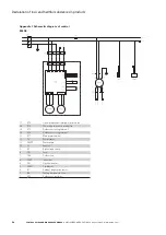
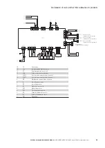
Page 58: ...inal of internal fan 16 XT4 Power plug terminal of internal fan 15 XT3 Outdoor unit wiring terminal 2 14 XT4 Outdoor unit wiring terminal 1 13 XT1 Main power terminal 12 SJ Water sensor 11 PUMP Water pump 10 L3 Reactor 9 KP High voltage switch 8 FU1 Fuse 7 FAN Outdoor fan 6 FAN1 Indoor fan 1 5 EH1 Electrical heater 4 COMP Compressor 3 B7 Ambient temperature sensor 2 B6 Venting temperature sensor 1...

Page 59: ...ce 15 TC Transformer 14 Sen Temperature and humidity sensor 13 RS Over heated protection switch 12 T H Sensor communication interface 11 PORT2 Host computer communication interface 2 10 PORT1 Host computer communication interface 1 9 MT Maintenance communication interface 8 LL Low water level switch 7 LPS Low voltage sensor 6 HL High water level switch 5 HPS High voltage sensor 4 EEV Electronic ex...

Page 60: ...l of internal fan 16 XT4 Power plug terminal of internal fan 15 XT3 Outdoor unit wiring terminal 2 14 XT4 Outdoor unit wiring terminal 1 13 XT1 Main power terminal 12 SJ Water sensor 11 PUMP Water pump 10 L3 Reactor 9 KP High voltage switch 8 FU1 Fuse 7 FAN Outdoor fan 6 FAN1 Indoor fan 1 5 EH1 Electrical heater 4 COMP Compressor 3 B7 Ambient temperature sensor 2 B6 Venting temperature sensor 1 AP...

Page 61: ...ical heater relay 15 TC Transformer 14 Sen Temperature and humidity sensor 13 RS Over heated protection switch 12 T H Sensor communication interface 11 PORT2 Host computer communication interface 2 10 PORT1 Host computer communication interface 1 9 MT Maintenance communication interface 8 LL Low water level switch 7 LPS Low voltage sensor 6 HL High water level switch 5 HPS High voltage sensor 4 EE...

Page 62: ...d to prices are reserved so are errors and omissions Only order confirmations and technical documentation by Eaton is binding Photos and pictures also do not warrant a specific layout or functionality Their use in whatever form is subject to prior approval by Eaton The same applies to Trademarks especially Eaton Moeller and Cutler Hammer The Terms and Conditions of Eaton apply as referenced on Eat...

Reviews: