EATON ELECTRICAL
30
Predictive Diagnostics
NOTES:
1. For motors an unused RTD can be used as the temperature sensor (wire colors in brackets
relate only to TS sensor) .
2. For switchgears current sensor (CT) is not used.
3. Use a left fitting (hub) on the enclosure for power supply cable and for the cables to the relays
(Alarm1&2, R3) and use a right hub for all signal cables.
4. FUSES: Miniature Fuses 5x20, 250VAC, 195 Series by Wickmann ( Distributor - DigiKey.com).
Fuse inside Insulgard for 120V application - 80mA ( DigiKey Part NO: WK5026-ND),
Fuse on the panel: 1.0A (DigiKey Part NO: WK5048-ND).
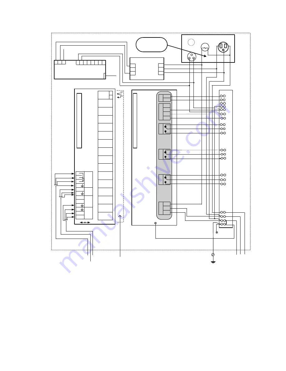
Sample InsulGard Panel Wiring Diagram, Revision 1
Coaxial cables
from PD sensors
C
o
n
n
e
c
to
r
to
I
n
s
u
lG
a
rd
C
o
a
x
c
a
b
le
s
f
ro
m
P
D
S
e
n
s
o
rs
#
#
1
-1
6
Ch1
Ch2
Ch4
Ch3
Ch5
Ch6
Ch8
Ch7
Ch9
Ch10
Ch12
Ch11
Ch13
Ch14
Ch16
(Noise)
Ch15
T
S
e
n
s
o
r
In
te
rf
a
c
e
B
o
a
rd
RTD
CT
H%
S
+5
S
Ref
5
S1
S2
6
7
8
9
10
11
12
4
3
2
1
Cables
from:
Temperature
sensor (TS)
Current sensor
(CT)
Humidity sensor
(HS)
red
blk
white
red
blk
(red)
(white)
(blk)
X1
X2
PC cable
to temporary
brought laptop
In
s
u
lG
a
rd
+
4
-2
0
m
A
A
la
rm
2
G
L
N
P
o
w
e
r
-
+
5
G
B
A
R
S
-
4
8
5
R
3
A
la
rm
1
C
o
n
n
e
c
to
r
to
I
n
te
rf
a
c
e
B
o
a
rd
blue all
blue
all
black
black
black
red
white
green
all
all
all
Screw for
panel
grounding
Screw on back
cover
G N L
115/230VAC
60/50 Hz, 10 A
Ground bolt
on enclosure
3
4
6
7
8
9
10
11
12
13
14
16
17
18
19
20
T
e
rm
in
a
l
s
tr
ip
1
2
5
15
L
G
N
re
d
w
h
it
e
g
re
e
n
1
2
Local Port
FUSE
1Amp
Outlet
120VAC-10Amp
1
2
Neutral PD
b
lu
e
a
ll
b
la
c
k
w
h
it
e
Phone
jack
Outgoing
phone
cable
1
1
1
0
9
Modem 1442M-920-2
(optional)
1
3
8
7
5
6
4
2
g
re
e
n
to
s
c
re
w
o
n
p
a
n
e
l
85-264VAC/
12VDC,1.3A
POWER
MODULE
+V
NC
-V
AC
AC
Gr
red
white
green
3
g
re
e
n
re
d
w
h
it
e
g
re
e
n
A
la
rm
S
ta
tu
s
W
a
rn
in
g
shield
shield
shield
H%
Ref
Sw
g
re
e
n
WD2-1
Diagram
Identifier
Figure 6-2 Typical connection diagram Revision 1
Sample !!!
Actual Schematic in
IG Enclosure


