UPS System Installation
4-10
Eaton 9EHD UPS (80-200 kVA, 380/400/415V) Installation and Operation Manual
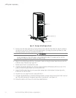
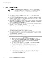
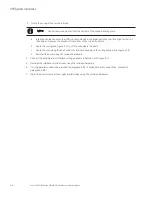
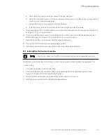
3. Route the wiring to the terminal block:
Conduit and wiring enter from the central of the conduit landing plate.
NOTE
a. Interface cables can enter the UPS via right side panel or a knockout in the top (front/right corner) of
the cabinet. Remove the knockout from either of the two entry points.
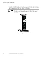
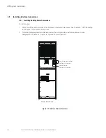
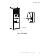
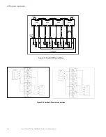
b. Route the wiring (see Figure 4-12) until the wire clears the shelf.
c. Route the wire along the shelf under the interface housing to the wiring access (see Figure 4-12).
d. Reinstall the cover using the retained hardware.
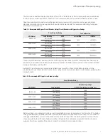
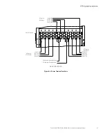
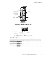
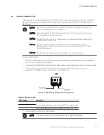
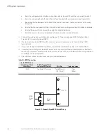
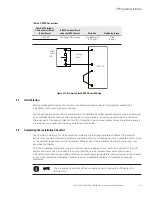
4. Connect the building alarm interface wiring as shown in Table 4-1 and Figure 4-11.
5. Reinstall the interface terminal cover using the retained hardware.
6. If wiring parallel connections, proceed to paragraph 4.5.2; if wiring Mini-Slot connections, proceed to
paragraph 4.5.3;
7. Install the power terminal cover right and left sides using the provided hardware.
Summary of Contents for 9EHD Series
Page 81: ......
Page 82: ...614 0 00...


