background image

Step 4

Cable insulation cutback


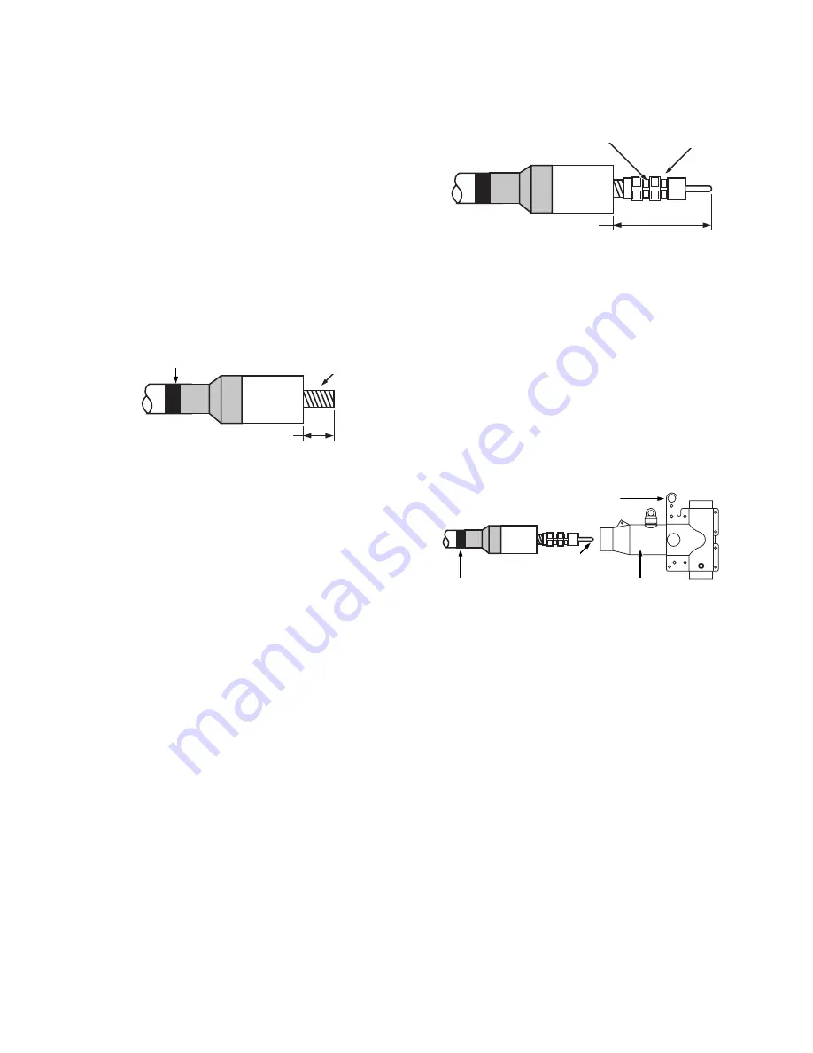
There should be between 4-3/8" and 4-11/16" of exposed 

cable beyond the cable adapter. Cut the cable insulation 

even with the end of the cable adapter and remove the 

protruding cable insulation. Take care not to cut the cable 

adapter or nick the conductor.

ote:

N

Alternate insulation removal method


The use of certain insulation removal tools may 

require cutting the insulation back before installing 

the cable adapter. After removing the semi-

conducting insulation shield, it is acceptable to first 

remove 4-1/2" of insulation from the end of the cable. 

Then put a 1/8" maximum chamfer in the insulation 

and install the cable adapter.

Step 5

Install compression connector


Wire brush aluminum conductor and immediately press 

compression connector onto the cable until the conductor 

bottoms. Copper conductors do not need to be wire 

brushed.


Rotate the connector so the spade eye faces the 

bushing.


Crimp the connector using a tool and die combination on 

the chart packaged with the connector.


Start crimping just below the first line from the spade 

end of the connector.


Rotate each successive crimp working towards the cable 

adapter. Do not overlap crimps.


Clean excess inhibitor from the compression connector 

and cable adapter surfaces.


After crimping, the distance from the cable adapter to the 

end of the compression connector must be between  

6-1/2" and 7-1/4". Refer to Figure 6.

Step 6

Install PDT625 PUSH-OP body


Clean and then lubricate outside of cable adapter.


Clean and lubricate inside of PUSH-OP Body.


Align PUSH-OP body so that operating eye is oriented 

away from apparatus bushing.


Slide PUSH-OP body onto cable until compression 

connector eye is centered between 600 A interfaces. 

(Refer to Figure 7.)


Remove tape marker from cable.

Figure 7.  Figure 7. Install T-body.

OPERATING EYE

TAPE MARKER

LUBRICATE

CA625

PUSH-OP T-BODY

Figure 5.  Remove cable insulation.

TAPE MARKER

3

/

8

" (111 mm) - 4 

11

/

16

" (119 mm)

CA625

CABLE 

CONDUCTOR

Figure 6.  Install compression connector.

CA625

PLACE FIRST  

CRIMP HERE

COMPRESSION CONNECTOR

1

/

2

" – 7 

1

/

4

"  

(165 mm-184 mm) CHECK 

DIMENSION AFTER CRIMPING

3

600 A 15/25 KV CLASS PUSH-OP DEADBREAK CONNECTOR INSTALLATION INSTRUCTIONS

   MN650057EN   May 2017

Summary of Contents for 600 A 15 kV class push-OP

Page 1: ...600 A 15 25 kV class PUSH OP deadbreak connector installation instructions COOPER POWER SERIES Deadbreak Apparatus Connectors MN650057EN Effective May 2017 Supersedes May 2014 S600 13 3...

Page 2: ...TING CONTRACT BETWEEN THE PARTIES ANY SUCH CONTRACT STATES THE ENTIRE OBLIGATION OF EATON THE CONTENTS OF THIS DOCUMENT SHALL NOT BECOME PART OF OR MODIFY ANY CONTRACT BETWEEN THE PARTIES In no event...

Page 3: ...ON Introduction 1 Handling and storage 1 Standards 1 INSTALLATION INSTRUCTIONS Equipment required 2 Cable preparation 2 Install PUSH OP connector on apparatus bushing 5 iii 600 A 15 25 KV CLASS PUSH O...

Page 4: ...formation DANGER Hazardous voltage Contact with hazardous voltage will cause death or severe personal injury Follow all locally approved safety procedures when working around high and low voltage line...

Page 5: ...carrier immediately Handling and storage Be careful during handling and storage of the PUSH OP deadbreak connector to minimize the possibility of damage If the connector is to be stored for any lengt...

Page 6: ...ded longitudinally corrugated wire shielded or UniShield use Eaton s SA series adapter kit with the same cutback dimensions as concentric neutral below If another manufacturer s metallic shield adapte...

Page 7: ...d with the connector Start crimping just below the first line from the spade end of the connector Rotate each successive crimp working towards the cable adapter Do not overlap crimps Clean excess inhi...

Page 8: ...e the alignment segment from the LRTP Recycle the align ment segment See Figure 9 for illustration of completed LRTP installation Step 8 Install probe Place tin plated copper PUSH OP probe with stud o...

Page 9: ...2 Release operating eye from clampstick Push forward on push plate firmly with clampstick until a bump is felt and latch plate fully engages locking teeth Refer to Figure 13a Pull on push plate with c...

Page 10: ...push plate while threading locking pin as this can cause the latch plate to become disengaged from the locking teeth This condition can cause the PUSH OP deadbreak connector to come off of the bushing...

Page 11: ...e to LRTP grounding tab and shroud grounding tab Connect drain wire to PUSH OP body grounding tab and shroud grounding tab Connect one strand of cable concentric neutral to shroud grounding tab Connec...

Page 12: ...s Eaton com cooperpowerseries 2017 Eaton All Rights Reserved Printed in USA Publication No MN650057EN Rev 00 Supersedes S600133 Rev2 SAFETY FOR LIFE Eaton is a registered trademark All trademarks are...

Reviews: