6.1.10
Thoroughly clean the seal grooves in the piston
and apply a thin, even coat of Parker " O" Lube
®
to the seal grooves, the seals, the sealing
surfaces of the cylinder and to the chamfer on
the piston.
6.1.11
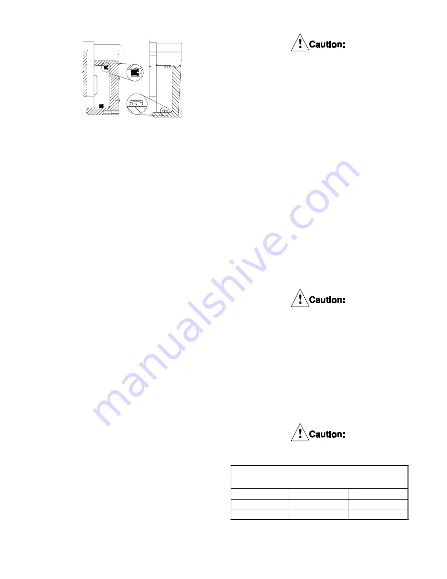
Install the new seals in the grooves in the
piston, noting the orientation of the seals in
Figure 17.
6.1.12
Turn the cylinder over so that the cavity faces
upw ard.
6.1.13
Carefully place the piston into the cylinder w ith
the chamfered edge of the inner diameter
facing dow nw ard into the cylinder taking
special care to avoid damaging the seal lips.
6.1.14
Gradually apply an evenly distributed force to
press the piston into the cylinder being sure
not to cock the piston w hich may damage the
sealing surfaces.
6.1.15
Using a lifting strap, slide the cylinder/piston
assembly onto the studs.
6.1.16
If not replacing friction disc, replace any w ear
spacers that w ere removed in 6.2.3 and install
(stored) under the locknuts for use after
replacing the friction discs. See Figure 12.
6.1.17
Lubricate the threads on the end of the studs
w ith 30 w t. oil or anti-seizing compound and
install the locknuts (18) w ashers (17) and the
w ear spacers removed.
6.1.18
While supporting the w eight of the
cylinder/piston assembly, tighten the locknuts,
ONE TURN AT A TIME and in an alternating
(crossw ise) pattern until the cylinder is seated
firmly against the clamp tubes. Torque the
locknuts to the appropriate value. See Table 4.
The locknuts (18) must be tightened
gradually to prevent damage to the
tensioner components.
6.1.19
Connect air supply line.
6.1.20
Perform an air test by applying 80 PSIG (5.5
bar) to engage the tensioner. Shut off the air
supply. If the air pressure does not drop below
70 PSIG (4.8 bar) after 10 minutes, the seals
have been properly installed.
6.2
Friction Lining Replacement for WCB’s
(with screwed on linings)
6.2.1
Friction disc cores may be relined w ith new
friction material per the follow ing instructions.
Refer to Section 11.0 for the appropriate
friction disc sub-assembly or friction disc re-
placement kit part number.
Note: Standard screw ed on friction lining is
identified w ith one notch, tw o places 180
o
apart, see Figure 18. High coefficient screw ed
on lining is identified w ith tw o notches, tw o
places 180
o
apart. See Figure 19.
Use only genuine Airflex friction material.
Use of material not of Airflex origin may
result in unpredictable performance.
6.2.2
Remove the old screw s and remove and
discard the old friction material.
6.2.3
Clean all burrs and corrosion from the
friction disc cores.
6.2.4
Apply Loctite
®
#262 to screw s and torque to
value show n in table 11.
Use only Airflex-supplied screws.
Fig. 17
8 & 14 WCB
18, 24 & 36
WCB
TABLE 11
Friction disc screw torque
P/N
Size
Torque
000153x1147
1/4-28UNRF
120 in lbs
000294x0407
1/2-13NC2
15 ft lbs
PDF FORMAT
25
© Copyright Eaton Corp., 1995. All rights reserved.
Summary of Contents for 146246A
Page 5: ...18 24 36 WCB Single Disc Figure 4 PDF FORMAT 4 Copyright Eaton Corp 1995 All rights reserved ...
Page 6: ...18 24 36 WCB Dual Disc Figure 5 PDF FORMAT 5 Copyright Eaton Corp 1995 All rights reserved ...
Page 7: ...18 24 36 WCB Triple Disc Figure 6 PDF FORMAT 6 Copyright Eaton Corp 1995 All rights reserved ...
Page 8: ...Figure 7 18 24 36 WCB Quad Disc PDF FORMAT 7 Copyright Eaton Corp 1995 All rights reserved ...


