TABLE 4
Fastener Description and Assembly Torque - ft-lb (Nm) (Lubed)
Fastener
8WCB
14WCB
18WCB
24WCB
36WCB
Item #18
Description
1/2-13NC-3
3/4-10NC-3
3/4-10NC-3
1 1/8-7NC
Gr. 8
1 3/8-6NC
Gr. 8
Torque
60 (81)
150 (203)
150 (203)
500 (677)
750 (1016)
Item # 5
Description
#10-24NC
1/4NC2
5/16-18NC
5/16-18NC
3/8-16NC2
Torque
5 (7)
12 (16)
25(31)
25(31)
40(54)
Mounting
Screw
Description
1/2-13NC-2
Gr.8
5/8-11NC-2
Gr. 8
5/8-11NC-2
Gr. 8
5/8-11NC-2
Gr. 8
1-8NC2 Gr. 8
Quantity
4
6
10
10
14
Torque
70 (95)
150 (203)
150 (203)
150 (203)
660 (895)
2.1.2
Figures 2 and 8 and Table 1 show the mount-
ing dimensions for the tensioner to the
machine frame or reaction bracket. Note that
a male or female register may be used.
2.2
Alignment
2.2.1
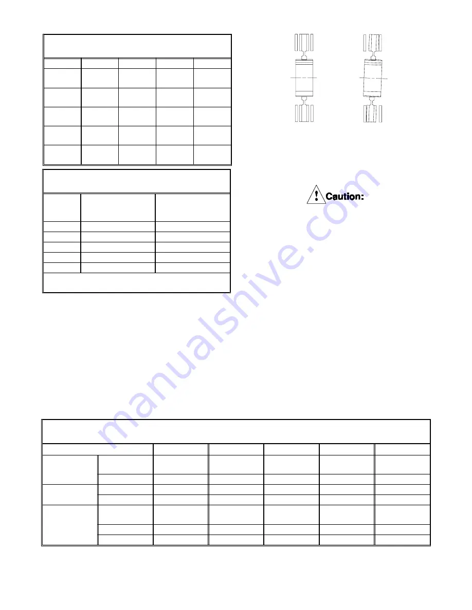
For proper operation and service life, the
tensioner reaction member must be aligned to
the shaft w ithin the limits show n on Table 3.
Proper alignment is necessary to ensure
that the friction discs track properly.
Improper alignment will result in
excessive wear to the friction material
and its mating surfaces, the gear and
splined bore of the friction disc
assembly. See Figure 9.
2.3 Mounting
2.3.1
The WCB must be mounted to a clean, rigid
surface w ith hardened flat w ashers and
screw s of the grade, quantity, and size and tor-
qued to the values identified in Table 4 for
each WCB size. Mounting to a rigid surface
minimizes any deflection during operation and
ensures that the friction discs w ill track
properly on the copper w ear plates.
Correct Track
Incorrect Track
Fig. 9
TABLE 2
"A" Dimension on Figure 1 - in. (mm)
Size
Single
Dual
Triple
Quad
8WCB
1.00
(25.4)
1.38
(35.0)
N/A
N/A
14WCB
1.06
(26.9)
1.69
(42.9)
N/A
N/A
18WCB
1.25
(31.8)
1.25
(31.8)
0.75
(19.1)
N/A
24WCB
1.38
(35.1)
1.00
(25.4)
0.63
(16.0)
1.38
(35.1)
36WCB
1.50
(38.1)
N/A
2.38
(60.5)
2.38
(60.5)
TABLE 3
Alignment Requirements
Size
Concentricity of
Shaft and Brake
In. (mm)
Perpendicularity of
Mounting Flange(2)
to Shaft - In. (mm)
8WCB
0.005 (0.13)
0.005 (0.13)
14WCB
0.010 (0.25)
0.007 (0.18)
18WCB
0.010 (0.25)
0.010 (0.25)
24WCB
0.010 (0.25)
0.012 (0.30)
36WCB
0.010 (0.25)
0.019 (0.48)
Perpendicularity referenced to outside diameter of
mounting flange from shaft center line (TIR).
PDF FORMAT
11
© Copyright Eaton Corp., 1995. All rights reserved.
Summary of Contents for 146246A
Page 5: ...18 24 36 WCB Single Disc Figure 4 PDF FORMAT 4 Copyright Eaton Corp 1995 All rights reserved ...
Page 6: ...18 24 36 WCB Dual Disc Figure 5 PDF FORMAT 5 Copyright Eaton Corp 1995 All rights reserved ...
Page 7: ...18 24 36 WCB Triple Disc Figure 6 PDF FORMAT 6 Copyright Eaton Corp 1995 All rights reserved ...
Page 8: ...Figure 7 18 24 36 WCB Quad Disc PDF FORMAT 7 Copyright Eaton Corp 1995 All rights reserved ...


