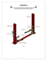
Eagle Equipment MTP-9F Installation & Operation Manual Download Page 14


14

STEP 4 


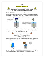
Securing the Main Side Post 

  BE VERY CAREFUL NOT TO DISTURB THE POSTS AT THIS POINT 


AS THEY MAY TIP OVER AND CAUSE PERSONAL INJURY.  


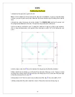
1]  Double  check  all  dimensions  and  make  sure  the  layout  is  square.  Verify  the  position  of  the 
Main Post within the square.  
 
2] Once the Main Side Post is in its final position, drill holes in the concrete using the base plate 
of the post as your template (Fig. 5). Use a ¾” hammer drill bit and drill straight clear holes.  Drill 
all the  way through the slab  when possible to allow for replacing an anchor if necessary.   Keep 
the hammer drill straight when drilling to prevent egging out the holes. 


          (Fig. 5) 


     (Fig. 6) 

 
3] Once holes are drilled, vacuum out the dust and insert anchor bolt(s) into hole(s) and tap down 
until  washer  rests  against  the  base  plate  (Fig.  6).  Be  sure  nut  is  flush  with  top  of  bolt  before 
tapping into hole.  

DO NOT TIGHTEN AT THIS TIME


CAUTION: Hitting the anchor bolts too hard   


may result in damaged threads, 

which may prevent proper tightening of the nut. 

Tap firmly, but carefully.


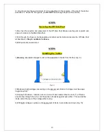
4] Before tightening the anchor bolts, check for plumb of the Main Side post with a 4’ level. Shim 
as necessary (Fig. 7).  Shims must be installed at all anchor points where there is a gap between 
the base plate and the concrete.  Do not shim more than ½”. 


    (Fig. 7)  


  (Fig. 8) 

 
5]  Once  the  Main  Side  post  is  positioned  and  shimmed  correctly,  secure  it  to  the  floor  by 
tightening the anchor bolts to 120 foot-pounds. 

DO NOT

 use an impact wrench (Fig. 8). 


Summary of Contents for MTP-9F

Page 1: ...BS CAPACITY TWO POST FLOOR PLATE LIFT INSTALLATION OPERATION MANUAL READ THIS MANUAL BEFORE INSTALLING OR OPERATING YOUR LIFT REV 20150420 SAY02 BD INSPECT YOUR LIFT UPON DELIVERY NOTE ANY DAMAGE ON D...

Page 2: ...Installing the Cables page 15 16 Step 7 Installing the Swing Arms page 17 Step 8 Installing the Swing Arm Restraints page 18 Step 9 Installing the Power Unit page 19 Step 10 Installing the Hydraulic F...

Page 3: ...ire pick up at a freight terminal An automotive lift is a heavy piece of equipment A fork lift or other similar mechanism is necessary for its loading off loading and movement Lifts cannot be unloaded...

Page 4: ...DO NOT operate or repair this equipment without reading this manual and the important safety instructions shown inside Keep these instructions accessible and make sure that ALL USERS read this manual...

Page 5: ...d when operating lift 12 Carefully inspect the lift on a regular basis Perform maintenance according to the maintenance schedule 12 Guard against electric shock This lift must be grounded while in use...

Page 6: ...nd washers securing the shipping brackets as these may be used in the assembly of the lift 3 The unit is composed of several main components See Fig 2 below 4 An Accessory Box is included with the lif...

Page 7: ...cks and depress the lowering handle Arms rotate and telescope for easy use Adapters are included for raising the height of the base pad at the end of the arm Swing arm locks automatically engage as th...

Page 8: ...8 Fig 2 NEVER ATTEMPT TO LIFT ANY PART OR PORTION OF A VEHICLE WITH LESS THAN ALL FOUR 4 ARMS AT ANY TIME...

Page 9: ...9 COMPONENTS It is a good idea to familiarize yourself with the components of your lift and the terms describing them Fig 3 Fig 3...

Page 10: ...onal lift installer is suggested Whoever installs the lift should read this manual thoroughly and familiarize themselves with its content A certified electrician is required for the final connection o...

Page 11: ...itect s plans when available Check layout dimension fig 2 against floor plan requirements making sure adequate space is available 2 OVERHEAD OBSTRUCTIONS The area where the lift will be located should...

Page 12: ...p between the base plate and the concrete Do not shim more than DO NOT install this lift on a second elevated floor without first consulting building architect DO NOT install this lift outdoors If you...

Page 13: ...etermined use a carpenter s chalk line to layout a grid for post locations Fig 4 Keep all dimensions and square of the dimensions within 1 8 or lift malfunction can occur Fig 4 4 First snap a center l...

Page 14: ...les Fig 5 Fig 6 3 Once holes are drilled vacuum out the dust and insert anchor bolt s into hole s and tap down until washer rests against the base plate Fig 6 Be sure nut is flush with top of bolt bef...

Page 15: ...Post as described in Step 5 numbers 1 6 above 3 Both posts are now secured STEP 6 Installing the Cables 1 Manually raise both carriages to rest on the second set of locks from the floor Fig 9 Fig 9 2...

Page 16: ...second cable an equal number of turns If done correctly both cables will tighten up an equal amount and neither carriage will lift off the locks as they are tightening against one another 7 Continue t...

Page 17: ...ms on the carriages Fig 11 2 Install the arm pins as shown Fig 11 NEVER ATTEMPT TO LIFT ANY PART OR PORTION OF A VEHICLE WITH LESS THAN ALL FOUR 4 ARMS AT ANY TIME NEVER RAISE VEHICLE WITHOUT ENSURING...

Page 18: ...carriage bracket to fully engage the Half Moon Gear on the arm Teeth of both gears should mesh when lift is raised When lift is lowered to the ground gears should completely disengage to allow arms t...

Page 19: ...4 5 16 x hex bolts flat washers lock washers and nuts Use the lower 2 pairs of slotted holes on the power unit bracket 3 Fill the reservoir to the fill line with hydraulic oil USE ONLY ISO 32 or AW 32...

Page 20: ...amb nut with a second wrench until the washer compresses the O ring Do not use Teflon tape STEP 11 Installing the Hoses 1 Connect one end of the short hydraulic hose to the elbow fitting at the pump C...

Page 21: ...onnect Fig 14 Fig 14 2 Wiring may vary depending on the Power Unit The typical connection is L1 to black power unit wire L2 to white power unit wire Neutral and Ground both connect to the chassis of t...

Page 22: ...lowering valve See illustration below Step 2 Using an Allen wrench and shop towel with shop towel in place to catch fluid loosen the check valve plug 2 1 2 turns to allow it to leak Step 3 Push the ST...

Page 23: ...ection is properly wired CHECK Power Unit Priming See Priming Procedure page 20 NOTE There will be some initial stretching of the cables in the beginning It will be necessary to re adjust the cables a...

Page 24: ...te 1 Secure the Floor Plate to the base of the columns using the Allen cap bolts and washers provided Floor Plate should cover the hose and cables without making contact with the cables Cables should...

Page 25: ...g height Lower vehicle onto nearest carriage safety lock before walking under the vehicle When working on a vehicle ALWAYS make sure that ALL LOCKS are engaged NEVER work beneath a vehicle without it...

Page 26: ...n wires in one strand 3 Replace the cables if you see corrosion or rusting on the wires or ends kinking crushed areas cutting spreading a cable core protruding or any other abnormality 4 If any cable...

Page 27: ...ydraulic flow is restricted Check hoses and fittings for blockage Check lowering valve for by pass CARRIAGES RAISE UNEVENLY 1 Uneven distribution of weight Vehicle improperly loaded or out of balance...

Page 28: ...ey 1622 Knob 1200 Tower Off Side 1605 Spring 1350 Floor Plate 1600 Arm Assembly Rear 1622 Knob 1601 Arm Pin 1900 Power Unit 220vac 1ph 1608 Cable Sheave Pulley 1902 Fitting 6 w Restrictor 1609 Rubber...

Page 29: ...03K Shim Rub Block 1704 Release Cable 1104 Cylinder 1705 Spring 1105 Chain Roller 1708 Set Bolt 1106 Pin Chain Roller 1902 Straight Fitting 1108 Nut Cable 1903 Elbow Fitting 1112 Cable 1905 Short Hose...

Page 30: ...________________________________________________ _______________________________________________________ _______________________________________________________ _______________________________________...

Page 31: ...are not limited to cables hoses slider blocks chains and rubber pads 3 On site labor Eagle Equipment reserves the right to make improvements and or design changes to its equipment without any obligati...

Page 32: ...n shops and car hobbyist including auto lifts frame machines pulling posts tire equipment painting accessories powder coating equipment sandblasting equipment paint booths and more One of the largest...

Reviews: