background image

0C08H

0C09H

0C0AH

0C0BH

0C0CH

0C06H

0C07H

60%

0

2.0s

0

3.00S

100%

810.0V

PC

-

08

PC

-

09

PC

-

10

PC

-

11

PC

-

12

PC

-

06

PC

-

07

50

100%

0: Fault 
1: Continue to operate within the allowable 
time of undervoltage recovery 
2: Continue to operate after the power supply 
returns to normal

0

.

1 60

.

0s

0: Invalid     1: Valid

0.0 120.00s

115.0

140.0%

0

2500.0V

Undervoltage 

threshold

Solution of 

undervoltage 

fault

Allowable time 

of undervoltage 

recovery

Restart method 

after power 

failure

Waiting time 

for restart 
after power 

failure

Action voltage of 

energy consumption 

braking

Overvoltage 

threshold

0C05H

10

PC

-

05

0

100

Current detection 

compensation

PD


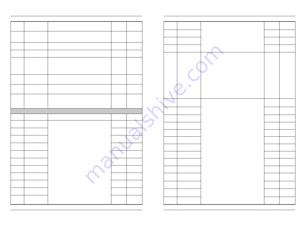
Internal control PLC Function and frequency parameters

Address

0D00H

Default


0.0%

Function 

Code

PD

-

00

Setting Range

Parameter Name

Multi-

frequency 1

0D01H

PD

-

01

Multi-

frequency 2

0D02H

PD

-

02

Multi-

frequency 3

0D03H

PD

-

03

Multi-

frequency 4

0D04H

PD

-

04

Multi-

frequency 5

0D05H

PD

-

05

Multi-

frequency 6

0D06H

PD

-

06

Multi-

frequency 7

0

100.0%

Multi segment instruction can be used in three 
situations: as frequency source, as voltage 
source separated by VF, as setting source of 
process PID.
As a frequency source, it is the percentage of 
relative maximum frequency;
As VF separated voltage source, it is the 
percentage of rated voltage relative to motor;
As the relative value of PID, it does not need 
dimension conversion.

0D07H

PD

-

07

Multi-

frequency 8

0D08H

PD

-

08

Multi-

frequency 9

0D09H

PD

-

09

Multi-

frequency 10

0D0AH

PD

-

10

Multi-

frequency 11

0D0BH

0.0%

PD

-

11

Multi-

frequency 12

0D0CH

0.0%

PD

-

12

Multi-

frequency 13

0D0DH

0.0%

PD

-

13

Multi-

frequency 14

0D0EH

0.0%

PD

-

14

Multi-

frequency 15

Multi segment instructions need to be selected 
according to different states of multi-
functional digital S. Please refer to P4 group 
for details.

0D0FH

0000

PD

-

15

PLC 

running mode

BIT0: Circulation mode 
0: Stop after the AC drive runs one cycle
1: Repeat after the AC drive runs one cycle
2: Keep final values after the AC drive runs 
one cycle
BIT1:Chronograph unit
0: Second    1: Minute    2: Hour
BIT2: Power down storage mode
0: No        1: Yes
BIT3: Start-up mode
0: Rerun from stage one
1: Rerun from downtime
2: Continue operation with the rest of the 
downtime phase

0D10H

10.0

PD

-

16

Running time of 
PLC reference 1

0D11H

10.0

PD

-

17

Running time of 
PLC reference 2

0D12H

10.0

PD

-

18

Running time of 
PLC reference 3

0D13H

10.0

PD

-

19

Running time of 
PLC reference 4

0D14H

10.0

PD

-

20

Running time of 
PLC reference 5

0D15H

10.0

PD

-

21

Running time of 
PLC reference 6

0D16H

10.0

PD

-

22

Running time of 
PLC reference 7

0D17H

10.0

PD

-

23

Running time of 
PLC reference 8

0D18H

10.0

PD

-

24

Running time of 
PLC reference 9

0D19H

10.0

PD

-

25

Running time of 

PLC reference 10

0D1AH

10.0

PD

-

26

Running time of 

PLC reference 11

0.0

6500.0

s/m/h)

0D1BH

10.0

PD

-

27

Running time of 

PLC reference 12

0D1CH

10.0

PD

-

28

Running time of 

PLC reference 13

0D1DH

10.0

PD

-

29

Running time of 

PLC reference 14

3 9

 -

4 0

 -

  F u n c t i o n C o d e T a b l e

EC620


EC620


  F u n c t i o n C o d e T a b l e

0.0%

0.0%

0.0%

0.0%

0.0%

0.0%

0.0%

0.0%

0.0%

0.0%

Summary of Contents for EC620

Page 1: ...Drive Manufacturer EC620 Solar Pump AC Drive Electronic instruction Professional AC Drive Manufacturer ZHEJIANG EACN ELECTRONIC TECHNOLOGY CO LTD Address No 1 Jinhe Road Qinshan Street Haiyan County J...

Page 2: ...arameters 7 5 P4 Input Terminals Function 7 6 P5 Analog Terminal Parameters 7 7 P6 Start Stop Control Parameters 7 8 P7 System Configuration Parameters 7 9 P8 Auxiliary Functions 7 10 P9 Fault and Pro...

Page 3: ...pply is cut off but the indicator light of the mani pulator of AC drive is still on there is still high voltage in the AC drive which is very dangerous please do not touch the interior circuit and com...

Page 4: ...ignal PLC needs to be connected to external power supply and be disconnected from 24V power supply terminal 1 Input voltage range DC 0V 10V 2 Impedance 22k 1 Input range DC 0V 10V 4mA 20mA decided by...

Page 5: ...he startup operation is performed on the rotating motor 7 A sudden load is added during acceleration 8 The AC drive model is of too small power class 1 The output circuit is grounded or short circuite...

Page 6: ...power input is abnormal 2 The drive board is faulty 3 The lightening board is faulty 4 The main control board is faulty 1 Eliminate external faults 2 Seek technical support 3 Seek technical support 4...

Page 7: ...erform the motor autotuning 3 Set P9 40 and P9 41 correctly based on the actual situation 7 Function Code Table Function Code Table EC620 Faults and solutions EC620 P0 Standard Parameter group 0000H A...

Page 8: ...Restore default setting 0017H 3 6 Undefined 7 Initialization setting User data reset 10 Back up current user parameters 210 Restore user backup parameters 0 210 P1 Motor parameters Setting Range Func...

Page 9: ...eleration process of AC drive the overexcitation control can restrain the rise of bus voltage and avoid over voltage fault The larger the overexcitation gain the stronger the suppression effect 64 020...

Page 10: ...the gain is the more obvious the suppression of the oscillation is When using the vibration suppression function the motor rated current and no load current parameters shall be accurate otherwise the...

Page 11: ...rence ability is but the slower the response speed is the shorter the filtering time is the weaker the anti interference ability is but the faster the response speed is Filter time of terminal S1 S4 0...

Page 12: ...put signal selection AI1 input voltage minimum value BIT2 AI3 signal selection 0 0 10V 1 0 20 00ma BIT3 S8 enable HDI function 0 General switch function 1 HDI high speed pulse input function 0 00 10 0...

Page 13: ...0 200 0 Used to adjust the value of analog output of AO1 terminal 10 0 10 0 Used to adjust the zero point of the AO1 terminal output signal 100 0 0 0 P5 35 P5 36 P5 37 0523H 0524H 0525H 100 0 0 0 0 20...

Page 14: ...vibration when the machine starts stops After setting the S word characteristic time the accelera tion and deceleration time will only extend 1 2 of the S word characteristic time at the beginning and...

Page 15: ...nly BIT0 0 Stop 1 Run BIT1 0 Forward RUN 1 Reverse RUN BIT2 Reserved BIT3 Reserved AC drive status before power off P7 18 0712H Read only P8 Auxiliary Functions Function Code Parameter Name Setting Ra...

Page 16: ...of the AC drive The start up of the timer is completed by the external timer trigger terminal of the timer The timing starts from the reception to the external trigger signal After the timing time arr...

Page 17: ...HASE_INPUT 13 ERROR_LOSE_PHASE_OUTPUT 14 ERROR_OH_MODULE 15 ERROR_EXTERNAL EQUIPMENT 16 ERROR_COMMUNICATE 17 ERROR_CONTACTOR 18 ERROR_CURRENT_DETECTION 19 ERROR_AUTO TUNING 20 ERROR_ENCODER 21 ERROR_E...

Page 18: ...at instantaneous rise action 0 50s 0924H returns to normal the AC drive will acce lerate to the set frequency The basis for judging whether the bus voltage returns to normal is that the bus voltage is...

Page 19: ...the specification of no hardware detec tion input phase failure the input phase failure is detected by the change amplitude of bus voltage When the change amplitude of bus voltage is greater than P9...

Page 20: ...tial output PA 13 PID differential limit 0 10 0A0DH 0 00 650 00s PID given change time refers to the time required for PID given value to change from 0 0 to 100 0 PA 14 PID setting change time 0 00s 0...

Page 21: ...tion proportion setting Communication response delay 3 N 8 2 No check data format 8 stop bit 2 4 E 8 2 Even parity check data format 8 stop BIT 2 5 0 8 2 Odd Parity check data format 8 stop BIT 2 0 00...

Page 22: ...Multi frequency 9 0D09H PD 09 Multi frequency 10 0D0AH PD 10 Multi frequency 11 0D0BH 0 0 PD 11 Multi frequency 12 0D0CH 0 0 PD 12 Multi frequency 13 0D0DH 0 0 PD 13 Multi frequency 14 0D0EH 0 0 PD 14...

Page 23: ...ence 8 0D27H 0000 PD 39 Running direction and acceleration deceleration time of PLC reference 9 0D28H 0000 PD 40 Running direction and acceleration deceleration time of PLC reference 10 0D29H 0000 PD...

Page 24: ...12 100 00 2 00 100DH A0 13 Reserved 1009H A0 09 Minimum Error KP1 It determines the regulation intensity of the whole PID regulator The greater the P value is the greater the regulation intensity is...

Page 25: ...will be cleared and restored to the operation state 75 0 101AH A0 26 Full water level detection delay code is still valid when the switch value is full of water 5s 101BH A0 27 Wake up delay at full w...

Page 26: ...ers read only U Setting Range U Monitoring Parameters Function Code Parameter Name Default Address U 00 2110H Set frequency 1E00H AE 00 Timing time 1 AE Scheduled operation Parameters The three sets o...

Page 27: ...put Shielded twisted pair Close to AC drive ground terminal Coil Coil Shielded twisted pair Close to AC drive ground terminal Coil Shielded twisted pair Close to AC drive ground terminal Coil High spe...

Page 28: ...bias voltage and the factory value 24V port and PLC port are short circuited 3 Port S8 is restricted by function parameter P5 00 which can be used as high speed pulse input channel with maximum input...

Page 29: ...ication Number Distributor Contacts Date of delivery Address No 1 Jinhe Road Qinshan Street Haiyan County Jiaxing City Zhejiang Province Website www eacon cn E mail overseas eacon cc Warranty Service...

Reviews: