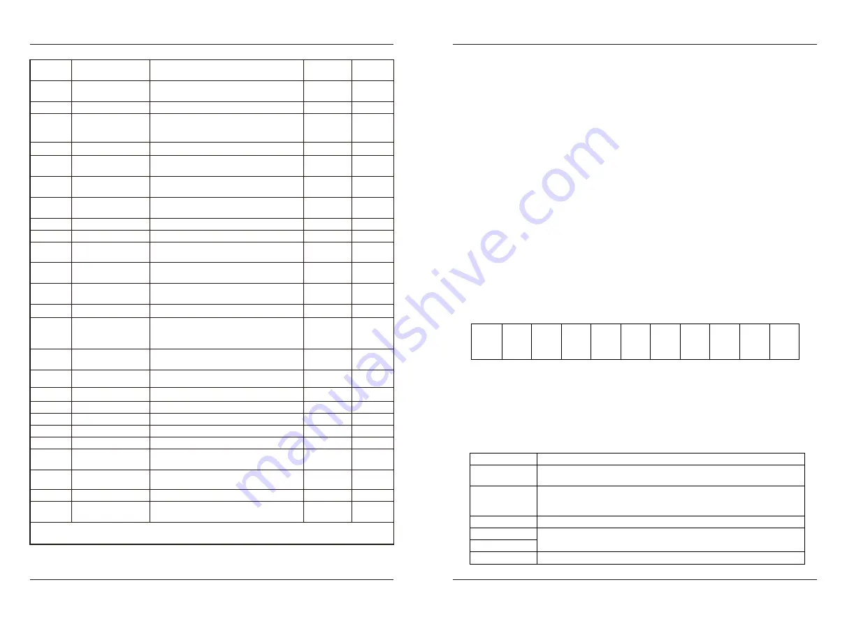
-
5 0
-
-
51
-
F u n c t i o n C o d e T a b l e
EC6000
U
-
29
-
212DH
-
AC drive
running state
U
-
30
U
-
31
-
-
212EH
212FH
-
-
Maximum
current
Maximum voltage
U
-
32
U
-
33
U
-
34
U
-
35
Rated power
of AC drive
Maximum
temperature of
this operation
Miniamum voltage
Rated voltage
of AC drive
-
-
-
-
-
-
-
-
2130H
2131H
2132H
2133H
U
-
36
U
-
37
U
-
39
U
-
40
Rated current
of AC drive
AC version
Communication
frequency
Main frequency
X display
-
-
-
-
-
-
-
-
2134H
2135H
2137H
2138H
U
-
41
Auxiliary frequency
Y display
-
-
2139H
U
-
38
MC version
-
-
2136H
Remaining time
U
-
42
-
-
213AH
U
-
43
U
-
44
U
-
45
Target voltage
upon V/F
separation
Output voltage
upon V/F separation
PG feedback value
-
-
-
-
-
-
213BH
213CH
213DH
U
-
46
Linear speed
-
-
213EH
U
-
48
U
-
49
U
-
50
Resolver position
ABZ position
Phase Z counting
-
-
-
-
-
-
2140H
2141H
2142H
U
-
47
PM rotor position
-
-
213FH
U
-
51
-
-
2143H
Communication
sending value
U
-
52
U
-
53
U
-
54
Communication
receiving value
Motor temperature
Multiple pumps
control
-
-
-
-
-
-
2144H
2145H
2146H
Press PRG key for 2 seconds continuously to enter the U monitoring parameter group item
*
R S 4 8 5 c o m m u n i c a t i o n p r o t o c o l
EC6000
10.RS485 communication protocol
●
Introduction to communication protocol
EC6000 series AC drive is equipped with RS485 communication interface as
standard, and adopts master-slave communication of international standard
ModBus communication protocol. Users can realize centralized control (set
converter control command、 operation frequency、 modification of relevant
function code parameters, monitoring of converter working status and fault
information, etc.) through PC / PLC, master computer, main station A
C
drive
,
etc., to adapt to specific application requirements.
●
Application mode
1. EC6000 series AC drive has a "single master and multi slave" control
network connected to RS485 bus. When the master uses the broadcast command
(slave address is 0), the slave does not answer.
2. EC6000 only provides RS485 interface, asynchronous half duplex. If the
communication port of external equipment is RS232, an additional RS232 /
RS485 converter is required.
3. Modbus protocol defines the information content and use format of
asynchronous transmission in serial communication, which can be divided into
rut mode and ASCII mode. EC6000 is RTU (remote terminal unit) mode.
●
Frames in Communication structure
The format of communication data is as follows:
Byte composition: including start bit, 8 data bits, parity bit and stop
bit.
Start
Bit
Stop
Bit
Parity
Bit
Bit1
Bit2
Bit3
Bit4
Bit5
Bit6
Bit7
Bit8
The information of a frame must be transmitted in a continuous data str-
eam. If the interval of more than 1.5 bytes before the end of the whole frame
transmission, the receiving device will clear these incomplete information
and mistakenly think that the next byte is the address domain part of the new
frame. Similarly, if the interval time between the start of a new frame and
the previous frame is less than 3.5 bytes, the receiving device will consider
it as the continuation of the previous frame. Due to the frame confusion, the
final CRC check value is not correct, resulting in communication errors.
Frame header
Frame tail
slave address
Command code
Data area
CRC CHK low
CRC CHK high
3.5 bytes transmission time
mail address:
0-247 (decimal) (0 is broadcast address)
03h: read slave parameters
06h: write slave parameters
08h: loop self test
Parameter address, number of parameters, parameter value, etc
Test value: 16 bit CRC test value
3.5 bytes transmission time


