background image

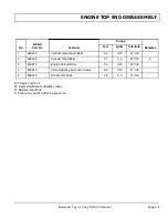
ENGINE TOP END DISASSEMBLY

Page A-3

Kawasaki Engine Shop Rebuild Manual

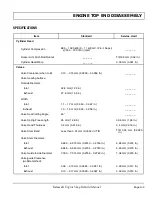
SPECIFICATIONS

Item

Standard

Service Limit

Cylinder Head

Cylinder Compression

880 ~ 1 080 kPa (9 ~ 11 kgf/cm², 128 ~156 psi) 

@ 500 ~ 700 r/min (rpm)

__ __ __

Rocker Arm Push Rod Runout

__ __ __

TIR 0.5 mm (0.02 in.)

Cylinder Head Warp

__ __ __

0.03 mm (0.001 in.)

Valves

Valve Clearance (when cold)

0.10 ~ 0.15 mm (0.0039 ~ 0.0059 in.)

__ __ __

Valve Seating Surface:

Outside Diameter:

    Inlet

32.8 mm (1.29 in.)

__ __ __

    Exhaust

27.6 mm (1.09 in.)

__ __ __

Width:

    Inlet

1.1 ~ 1.7 mm (0.043 ~ 0.067 in.)

__ __ __

   Exhaust

1.0 ~ 1.5 mm (0.039 ~ 0.059 in.)

__ __ __

Valve Seat Cutting Angle

45°

__ __ __

Valve Spring Free Length

35 mm (1.38 in.)

32.6 mm (1.28 in.)

Valve Head Thickness

0.4 mm (0.016 in.)

0.4 mm (0.016 in.)

Valve Stem Bend

Less than 0.01 mm (0.0004 in.) TIR

TIR 0.05 mm (0.0020

in.)

Valve Stem Diameter:

    Inlet

6.960 ~ 6.975 mm (0.2740 ~ 0.2746 in.)

6.95 mm (0.274 in.)

    Exhaust

6.945 ~ 6.960 mm (0.2734 ~ 0.2740 in.)

6.93 mm (0.273 in.)

Valve Guide Inside Diameter

7.000 ~ 7.015 mm (0.2756 ~ 0.2762 in.)

7.08 mm (0.279 in.)

Valve/guide Clearance

(wobble method):

    Inlet

0.06 ~ 0.13 mm (0.0024 ~ 0.0051 in.)

0.29 mm (0.011 in.)

    Exhaust

0.10 ~ 0.17 mm (0.0039 ~ 0.0067 in.)

0.33 mm (0.013 in.)

Summary of Contents for Engine

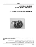
Page 1: ...19 17 18 13 6 5 9 15 16 7 8 10 4 3 11 1 INCLUDES ITEMS 3 16 4 STROKE AIR COOLED GASOLINE ENGINE STARTING MODEL YEAR 2008 KAWASAKI ENGINE SHOP REBUILD MANUAL 608172...

Page 2: ......

Page 3: ...the informa tion contained in this manual is subject to change without notice E Z GO Division of Textron Inc is not liable for errors in this manual or for incidental or consequential damages that re...

Page 4: ...BOVE FACTORY SETTINGS WILL VOID THE VEHICLE WARRANTY IF APPLICABLE REFER TO BACK COVER FOR CALIFORNIA AND OR FEDERAL EMISSIONS CONTROL WARRANTY STATEMENT Engine exhaust from this product contains chem...

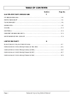
Page 5: ...sm A 2 SPECIFICATIONS A 3 EXPLODED VIEW A 4 ENGINE BOTTOM END DISASSEMBLY B ENGINE BOTTOM END Tool List B 1 CRANKCASE Remove Crankcase Cover B 1 CAMSHAFT AND TAPPETS Remove Camshaft Tappet B 1 CYLINDE...

Page 6: ...er C 9 Measure Valve Guide Inside Diameter C 9 Measure Valve Guide Clearance Wobble Method C 9 CAMSHAFT AND TAPPETS Measure Camshaft Bearing Journal Wear C 10 CYLINDER AND PISTONS Clean Piston C 11 Ch...

Page 7: ...Install Balancer Shaft D 1 CRANKSHAFT AND CONNECTING RODS Install Crankshaft D 2 Install Connecting Rod D 2 CYLINDERS AND PISTONS Install Piston D 2 CAMSHAFT AND PISTONS Install Camshaft Tappet D 4 CR...

Page 8: ...OOLING F 10 ELECTRICAL F 12 CARBURETOR CABLE BRACKETS F 14 AIR INTAKE BREATHER EXHAUST F 16 LIMITED WARRANTY G Federal Emissions Component Defect Warranty G 1 California Emission Control Warranty Stat...

Page 9: ...ginning of each major section is a list of tools that will be required to perform the operations desired in that sec tion Do not use non specified tools vise grips hammers adjustable wrenches etc The...

Page 10: ...Page viii Kawasaki Engine Shop Rebuild Manual Notes...

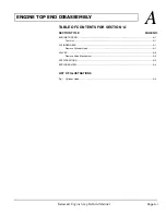
Page 11: ...Kawasaki Engine Shop Rebuild Manual A ENGINE TOP END DISASSEMBLY ENGINE TOP END A 1 Tool List A 1 CYLINDER HEAD A 1 Remove Cylinder Head A 1 VALVES A 2 Remove Valve Mechanism A 2 SPECIFICATIONS A 3 E...

Page 12: ...ENGINE TOP END DISASSEMBLY Kawasaki Engine Shop Rebuild Manual Page A ii Notes...

Page 13: ...moved only if they appear to be damaged or excessively worn Remove bearings that are pitted nicked burred discolored or that rotate roughly or noisily Because some mating parts with wear surfaces were...

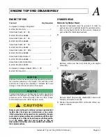
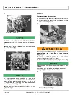
Page 14: ...occur if they are used as pry points Remove cylinder head bolts A push rod guides B and cylinder head C VALVES Remove Valve Mechanism A Remove cylinder head see Remove Cylinder Head B Support the valv...

Page 15: ...09 in __ __ __ Width Inlet 1 1 1 7 mm 0 043 0 067 in __ __ __ Exhaust 1 0 1 5 mm 0 039 0 059 in __ __ __ Valve Seat Cutting Angle 45 __ __ __ Valve Spring Free Length 35 mm 1 38 in 32 6 mm 1 28 in Va...

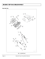
Page 16: ...ENGINE TOP END DISASSEMBLY Page A 4 Kawasaki Engine Shop Rebuild Manual Exploded View Fig 1 Cylinder Head...

Page 17: ...ollow the specific tightening sequence No E Z GO Part No Fastener Torque Remarks N m kgf m ft lb in lb 1 603523 Cylinder Head Cover Bolts 6 9 0 70 61 in lb 2 603525 Cylinder Head Bolts 37 3 8 27 ft lb...

Page 18: ...Page A 6 Kawasaki Engine Shop Rebuild Manual Notes...

Page 19: ...1 Remove Crankcase Cover B 1 CAMSHAFT AND TAPPETS B 1 Remove Camshaft Tappet B 1 CYLINDERS AND PISTONS B 2 Remove Piston B 2 CRANKSHAFT AND CONNECTING RODS B 3 Remove Connecting Rod B 3 Remove Cranks...

Page 20: ...ENGINE BOTTOM END DISASSEMBLY Page B ii Kawasaki Engine Shop Rebuild Manual Notes...

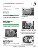
Page 21: ...If the crankcase cover sticks tap lightly with a wooden or plastic mallet near the dowel pins C B C Remove crankcase cover bolts A and crankcase cover B CAMSHAFT AND TAPPETS Remove Camshaft Tappet A...

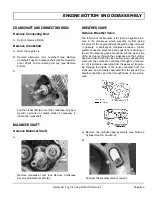
Page 22: ...ing rod cap bolts A C Remove the bolts and take off the connecting rod cap B Note the position of the connecting rod cap for reinstalling the cap D Push the connecting rod end into the cylinder and pu...

Page 23: ...n of the breather is to create a negative pres sure in the crankcase which prevents oil from being forced out of the engine through the piston rings oil seals or gaskets A sealed type crankcase emissi...

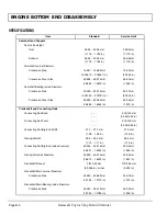
Page 24: ...Side 50 000 50 025 mm 50 09 mm 1 9685 1 9695 in 1 972 in Crankshaft and Connecting Rods Connecting Rod Bend 0 15 100 mm 0 006 3 94 in Connecting Rod Twist 0 15 100 mm 0 006 3 94 in Connecting Rod Big...

Page 25: ...74803 in 0 7465 in Piston Pin Hole Inside Diameter 19 004 19 015 mm 19 08 mm 0 74819 0 74862 in 0 7512 in Connecting Rod Small End Inside Diameter 19 010 19 021 mm 19 06 mm 0 74842 0 74886 in 0 7504 i...

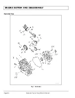
Page 26: ...ENGINE BOTTOM END DISASSEMBLY Page B 6 Kawasaki Engine Shop Rebuild Manual Exploded View Fig 1 Crankcase...

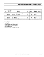
Page 27: ...lfide grease R Replacement Parts S Follow the specific tightening sequence No E Z GO Part No Fastener Torque Remarks N m kgf m ft lb in lb 1 603535 Connecting Rod Big End Cap Bolts 5 9 0 60 52 in lb E...

Page 28: ...Page B 8 Kawasaki Engine Shop Rebuild Manual Notes...

Page 29: ...Measure Valve Guide Inside Diameter C 9 Measure Valve Guide Clearance Wobble Method C 9 CAMSHAFT AND TAPPETS C 10 Measure Camshaft Bearing Journal Wear C 10 CYLINDER AND PISTONS C 11 Clean Piston C 1...

Page 30: ...ENGINE MEASUREMENTS Page C ii Kawasaki Engine Shop Rebuild Manual Notes...

Page 31: ...if the engine will see high usage Check micrometers for proper calibration before beginning the operations described in this section Using Telescoping Gauges and Hole Gauges Telescoping gauges and ho...

Page 32: ...il seal and or damaged piston oil rings Remove the carbon deposits and replace damaged parts if necessary Incorrect cylinder head gasket thickness Replace with a gasket of the proper thick ness Cylind...

Page 33: ...Rocker Arm Push Rod Runout Service Limit TIR 0 5 mm 0 02 in Inspect Rocker Arm A Clean and inspect the rocker arm where it touches the push rod and valve stem B If the contact points A are worn or dam...

Page 34: ...ide diameter D of the seating pat tern on the valve seat I If the outside diameter of the valve seating pattern is too large or too small repair the seat Valve Seating Surface Outside Diameter Inlet 3...

Page 35: ...h off any ground particles sticking to the cutter 5 After use wash the cutter with washing oil and apply a thin layer of engine oil before storing Marks Stamped on the Cutter The marks stamped on the...

Page 36: ...nce the seat width and O D are within the ranges specified above K Put a little coarse grinding compound on the face of the valve in a number of places around the valve head L Spin the valve against t...

Page 37: ...ENGINE MEASUREMENTS Page C 7 Kawasaki Engine Shop Rebuild Manual...

Page 38: ...ckness is less than the service limit replace the valve with a new one Valve Head Thickness Standard 0 4 mm 0 016 in Service Limit 0 4 mm 0 016 in Measure Valve Stem Bend A Place the valve in V blocks...

Page 39: ...mm 0 2756 0 2762 in Service Limit 7 08 mm 0 279 in Measure Valve Guide Clearance Wobble Method A If a small bore gauge is not available inspect the valve guide wear by measuring the valve guide clear...

Page 40: ...al Diameter Standard 19 967 19 980 mm 0 78610 0 78661 in Service Limit 19 94 mm 0 7850 in Crankcase Cover Side Camshaft Journal Diameter Standard 49 959 49 975 mm 1 9669 1 9675 in Service Limit 49 93...

Page 41: ...t will not cause damage Scrape the carbon off the piston head with a scraper A C Be careful not to widen the ring grooves Damaged ring grooves will require piston replacement D Clean the piston ring g...

Page 42: ...andard Top Second 1 47 1 49 mm 0 0579 0 0587 in Service Limit Top Second 1 40 mm 0 0551 in When using new rings in a used piston check for uneven groove wear The rings should fit perfectly parallel to...

Page 43: ...replace the piston Piston Pin Hole Inside Diameter Standard 19 004 19 015 mm 0 74819 0 74862 in Service Limit 19 08 mm 0 7512 in F Measure the inside diameter A of the small end of the connecting rod...

Page 44: ...of improper tooth contact C Replace the gear if necessary D Inspect the crankshaft and connecting rods espe cially at the bearing surfaces for wear scratches evi dence of improper contact or other da...

Page 45: ...ss than the service limit replace the connecting rod Connecting Rod Big End Width Standard 27 4 27 7 mm 1 08 1 09 in Service Limit 27 0 mm 1 06 in C Measure the crankpin width A with a dial caliper D...

Page 46: ...and lowest dial gauge readings TIR is the amount of runout E If the measurement exceeds the service limit replace the crankshaft Crankshaft Runout Standard TIR 0 02 mm 0 0008 in or less Service Limit...

Page 47: ...Standard 32 000 32 016 mm 1 2598 1 2605 in Service Limit 32 06 mm 1 262 in E Measure the inside diameter A of the balancer shaft bearing on the crankcase cover at several points F If inside diameter...

Page 48: ...Page C 18 Kawasaki Engine Shop Rebuild Manual Notes...

Page 49: ...List D 1 BREATHER VALVE D 1 Install Breather Valve D 1 BALANCER SHAFT D 1 Install Balancer Shaft D 1 CRANKSHAFT AND CONNECTING RODS D 2 Install Crankshaft D 2 Install Connecting Rod D 2 CYLINDERS AND...

Page 50: ...ENGINE BOTTOM END REASSEMBLY Page D ii Kawasaki Engine Shop Rebuild Manual Notes...

Page 51: ...the engine was manufactured or have estab lished wear patterns during operation the reassembly of engine parts in their original positions and orientations with their origi nal mating parts is critic...

Page 52: ...Connecting Rod A Refer to Install Piston CYLINDERS AND PISTONS Install Piston A Install the expander A in the piston oil ring groove so that the expander ends B touch never overlap B There is no up o...

Page 53: ...Apply engine oil to the piston skirt and the cylinder bore J Using the piston ring compressor grip A and the belt B lightly tap the top of the piston with a plastic mal let C to insert the piston and...

Page 54: ...ft gear and on the camshaft gear E Install the crankcase cover see Install Crankcase Cover F Install the push rods see Install Cylinder Head in Section A G Mount the rocker arms on the push rods and i...

Page 55: ...ASSEMBLY Page D 5 Kawasaki Engine Shop Rebuild Manual C Install the crankcase cover and tighten the crankcase cover bolts following the tightening sequence as shown Torque Crankcase Cover Bolts 22 N m...

Page 56: ...Page D 6 Kawasaki Engine Shop Rebuild Manual Notes...

Page 57: ...SECTION E SECTION TITLE PAGE NO Page E i E ENGINE TOP END REASSEMBLY Kawasaki Engine Shop Rebuild Manual ENGINE TOP END E 1 Tool List E 1 VALVES E 1 Install Valve Mechanism E 1 CYLINDER HEAD E 1 Inst...

Page 58: ...ENGINE TOP END REASSEMBLY Page E ii Kawasaki Engine Shop Rebuild Manual Notes...

Page 59: ...art No N A 1 VALVES Install Valve Mechanism A Apply engine oil to the valve stems and install them B Check to see that the valve moves smoothly up and down in the guide C Install the spring and the va...

Page 60: ...push rods on each cylinder are at the lowest position on the cam lobes D If not turn the alternator rotor clockwise one turn and position the crankshaft at TDC of the compres sion stroke I Be sure the...

Page 61: ...NO Page Fi F ILLUSTRATED PARTS BREAKDOWN Kawasaki Engine Shop Rebuild Manual CYLINDER CRANKCASE F 2 PISTON CRANKSHAFT F 4 VALVE CAMSHAFT F 6 LUBRICATION F 8 COOLING F 10 ELECTRICAL F 12 CARBURETOR CA...

Page 62: ...ILLUSTRATED PARTS BREAKDOWN Page Fii Kawasaki Engine Shop Rebuild Manual...

Page 63: ...F ILLUSTRATED PARTS BREAKDOWN Page F 1 Kawasaki Engine Shop Rebuild Manual Notes...

Page 64: ...ILLUSTRATED PARTS BREAKDOWN Page F 2 Kawasaki Engine Shop Rebuild Manual CYLINDER CRANKCASE...

Page 65: ...COVER CRANKCASE 603512 1 1 5 GASKET CAS COVER 603513 1 1 6 PLATE BREATHER 603514 1 1 7 VALVE BREATHER 603515 1 1 8 PIPE BREATHER 603516 1 1 9 COVER CRANKCASE 603517 1 1 10 CRANKCASE COMPLETE 603518 1...

Page 66: ...ILLUSTRATED PARTS BREAKDOWN Page F 4 Kawasaki Engine Shop Rebuild Manual PISTON CRANKSHAFT...

Page 67: ...em Description E Z GO Part Number Quantity GOLF UTILITY 20 PISTON ENGINE 603528 1 1 21 PIN PISTON 603529 1 1 22 RING SET PISTON 603530 1 1 23 CRANKSHAFT COMPLETE 603531 1 1 24 BALANCER COMPLETE 603532...

Page 68: ...ILLUSTRATED PARTS BREAKDOWN Page F 6 Kawasaki Engine Shop Rebuild Manual VALVE CAMSHAFT...

Page 69: ...6 1 1 29 VALVE EXHAUST 603537 1 1 30 RETAINER VALVE SPRING 603538 2 2 31 COLLECT 603539 4 4 32 ARM ROCKER 603540 2 2 33 TAPPET 603541 2 2 34 GUIDE PUSH ROD 603542 2 2 35 ROD PUSH 603543 2 2 36 SPRING...

Page 70: ...ILLUSTRATED PARTS BREAKDOWN Page F 8 Kawasaki Engine Shop Rebuild Manual LUBRICATION...

Page 71: ...603555 1 1 48 FILTER OIL FJ400D 607454 1 1 49 DIPSTICK OIL LOW SUSP 606390 1 1 50 DIPSTICK OIL HIGH SUSP NOT SHOWN 606391 1 51 RING SNAP 603556 1 1 52 PLUG 603557 3 3 53 BALL 603558 1 1 54 SPRING OIL...

Page 72: ...ILLUSTRATED PARTS BREAKDOWN Page F 10 Kawasaki Engine Shop Rebuild Manual COOLING...

Page 73: ...Kawasaki Engine Shop Rebuild Manual COOLING Item Description E Z GO Part Number Quantity GOLF UTILITY 59 SHROUD ENGINE 603563 1 60 GUARD 603564 1 1 61 FAN 603566 1 1 62 HOUSING FAN 603567 1 1 63 RIVE...

Page 74: ...ILLUSTRATED PARTS BREAKDOWN Page F 12 Kawasaki Engine Shop Rebuild Manual ELECTRICAL...

Page 75: ...ty GOLF UTILITY 65 PLATE FAN 603571 1 1 66 ASSY IGNITION COIL 603572 1 1 67 FLYWHEEL ASSEMBLY 607463 1 1 68 WIRE LEAD 603573 1 1 69 PLUG 603522 1 1 70 PLUG SPARK BPR2ES 607462 1 1 71 BOLT M12X39MM LG...

Page 76: ...ILLUSTRATED PARTS BREAKDOWN Page F 14 Kawasaki Engine Shop Rebuild Manual CARBURETOR CABLE BRACKETS...

Page 77: ...URETOR AS03 607954 1 81 CARBURETOR AS07 SPEC NOT SHOWN 607955 1 82 PLUG PILOT JET 603585 1 1 83 JET PILOT 44 608021 1 84 JET PILOT 52 NOT SHOWN 607957 1 85 JET MAIN 106 607956 1 86 JET MAIN 104 607683...

Page 78: ...ILLUSTRATED PARTS BREAKDOWN Page F 16 Kawasaki Engine Shop Rebuild Manual AIR INTAKE BREATHER EXHAUST...

Page 79: ...KE BREATHER Item Description E Z GO Part Number Quantity GOLF UTILITY 97 GASKET CHOKE 603593 1 1 98 PIPE INTAKE 603594 1 1 99 NUT M6X1 0 V 603595 2 2 100 CLAMP INTAKE PIPE 603596 1 1 101 CLAMP CYLINDR...

Page 80: ...ILLUSTRATED PARTS BREAKDOWN Page F 18 Kawasaki Engine Shop Rebuild Manual Notes...

Page 81: ...California Only G 5 CALIFORNIA EMISSION CONTROL WARRANTY STATEMENT 2000 G 8 YOUR WARRANTY RIGHTS AND OBLIGATIONS G 8 LIMITED WARRANTY on Emission Control Systems California Only G 8 CALIFORNIA EMISSI...

Page 82: ...LIMITED WARRANTY Page G ii Kawasaki Engine Shop Rebuild Manual Notes...

Page 83: ...assy gaseous fuel if applicable 2 Air Induction System i Intake manifold if applicable ii Air filter 3 Ignition System i Spark plugs ii Magneto or electronic ignition system iii Spark advance retard...

Page 84: ...not been properly maintained Warranty claims will not be denied however solely because of the lack of required maintenance or failure to keep maintenance records MAINTENANCE REPLACEMENT OR REPAIR OF...

Page 85: ...able 5 Miscellaneous Items Used in Above Systems i Electronic controls if applicable ii Hoses belts connectors and assemblies iii Filter lock assembly gaseous fuel if applicable OBTAINING WARRANTY SER...

Page 86: ...ENT OR REPAIR OF EMISSSION CONTROL DEVICES AND SYSTEMS MAY BE PERFORMED BY ANY REPAIR ESTABLISHMENT OR INDIVIDUAL HOWEVER WARRANTY REPAIRS MUST BE PERFORMED BY A DISTRIBUTOR DEALER OR SERVICE PROVIDER...

Page 87: ...E Z GO DIVISION OF TEXTRON INC Augusta Georgia herein E Z GO to which FUJI supplies the en gine as soon as a problem exists The warranty repairs should be completed in a reasonable amount of time not...

Page 88: ...distributors or warranty stations authorized by E Z GO In the event that any emission related part is found to be defective during the warranty period you should notify E Z GO Warranty Department at...

Page 89: ...scheduled maintenance below is based on the normal engine operating schedule PROCEDURE INTERVAL a Check for sealing of fuel cap and proper operation of fuel gauge at each fueling Check that fuel cap v...

Page 90: ...O DIVISION OF TEXTRON INC Augusta Georgia herein E Z GO to which FUJI supplies the en gine as soon as a problem exists The warranty repairs should be completed in a reasonable amount of time not to ex...

Page 91: ...stributors or warranty stations authorized by E Z GO In the event that any emission related part is found to be defective during the warranty period you should notify E Z GO Warranty Department at 1 8...

Page 92: ...f that inspection and maintenance services are performed at the times when recommended FUJI will not deny a warranty claim solely be cause you have no record of maintenance however FUJI may deny a war...

Page 93: ...herein Textron Golf Turf Specialty Prod ucts to which FUJI supplies the engine as soon as a problem exists The warranty repairs should be com pleted in a reasonable amount of time not to exceed 30 da...

Page 94: ...the event that any emission related part is found to be defective during the warranty period you should notify Textron Golf Turf Specialty Products Warranty Department at 1 800 241 5855 and you will...

Page 95: ...times recommended in the 2001 and later Owner s Manual and to retain proof that inspection and maintenance services are performed at the times when recommended FUJI will not deny a warranty claim sol...

Page 96: ...Z GO Division of Textron Augusta Georgia herein E Z GO to which FUJI supplies the engine as soon as a problem exists The warranty repairs should be completed in a reasonable amount of time not to ex c...

Page 97: ...E Z GO In the event that any emission related part is found to be defective during the warranty period you should notify E Z GO Warranty Department at 1 800 241 5855 and you will be given the appropri...

Page 98: ...es performed at the times recom mended in the 2004 and later Owner s Manual and to retain proof that inspection and maintenance services are per formed at the times when recommended FUJI will not deny...

Page 99: ......
Page 100: ...the express permission of E Z GO Division of Textron Inc Technical Communications Department E Z GO Division of Textron Inc 1451 Marvin Griffin Rd Augusta Georgia 30906 USA Inside USA Phone 1 800 241...

Reviews: