


CHECKING SWITCH CONTINUTY
ELEC
7 - 3
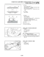
OFF
ON
Br R/W
a
b
CHECKING SWITCH CONTINUITY
Check each switch for continuity with the poc-
ket tester. If the continuity reading is incorrect,
check the wiring connections and if necessary,
replace the switch.
NOTICE:
Never insert the tester probes into the cou-
pler terminal slots. Always insert the probes
from the opposite end of the coupler, taking
care not to loosen or damage the leads.
TIP:
• Before checking for continuity, set the poc-
ket tester to “0” and to the “ Ωx1” range.
• When checking for continuity, switch back
and forth between the switch positions a
few times.
The terminal connections for switches (e.g.,
main switch, engine stop switch) are shown in
an illustration similar to the one on the left.
The switch positions
a are shown in the far
left column and the switch lead colors b are
shown in the top row in the switch illustration.
TIP:
“
—
” indicates a continuity of electricity
between switch terminals (i.e., a closed circuit
at the respective switch position).
The example illustration on the left shows
that:
There is continuity between red and brown
when the switch is set to “ON”.
Pocket tester
0
Ωx1
∞


