background image

DYSIS Ultra 2.0 Digital Colposcope Instructions for Use 
0330-53095 R4 
Revision Date 25-Feb-2021 


Page 

13

 of 

61


10.1.


Base/Moving the Instrument  

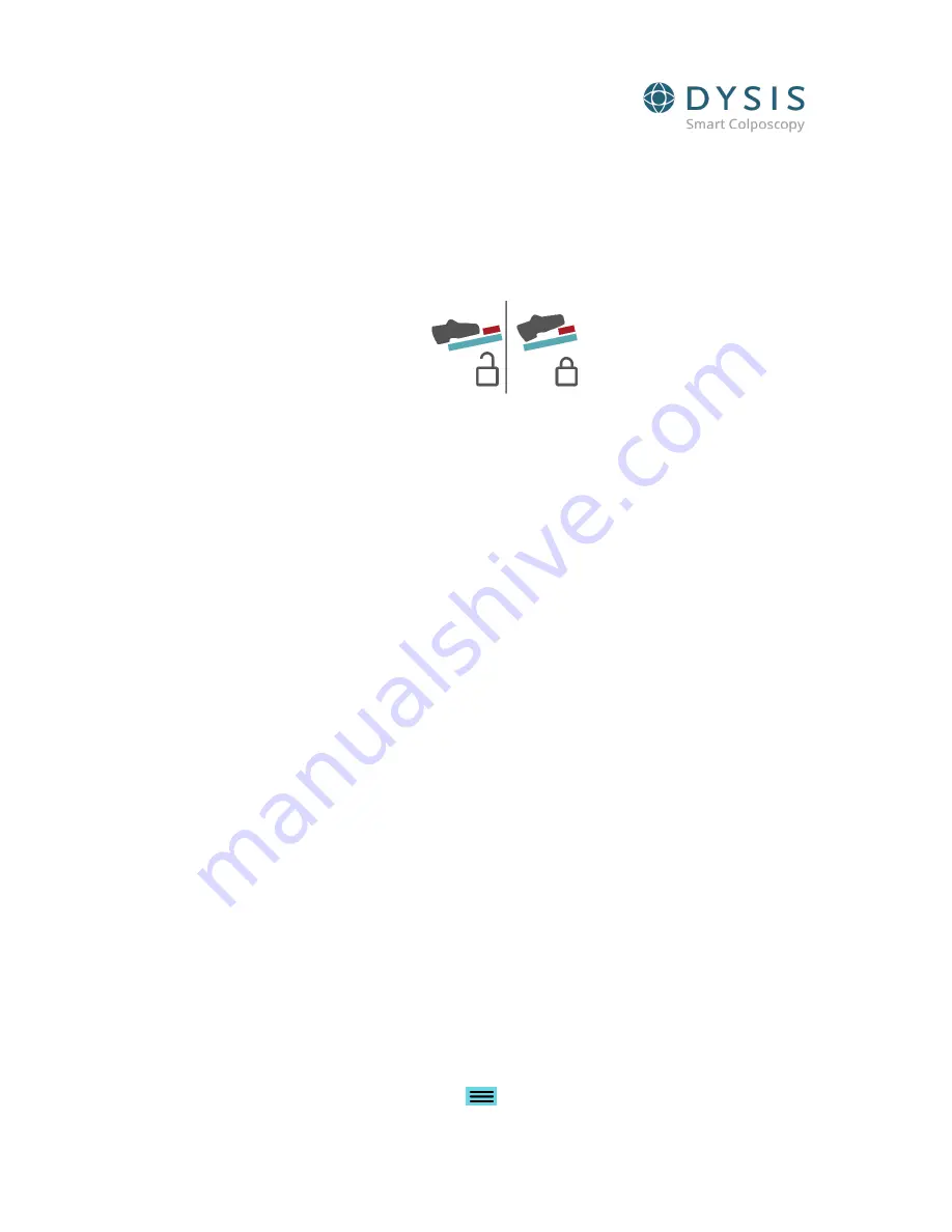
On the base, there is a foot pedal to engage/disengage the brake. To move the DYSIS Ultra 2.0 Digital Colposcope, 
the brake should be disengaged. To disengage the brake, push the green pedal down with your foot (Fig 5). When 
in a suitable position, the red switch on the pedal should be pressed with your foot to engage the brake. Do not 
use your hands to engage the brake. 


Fig 5: DYSIS Ultra 2.0 foot pedal 

When moving DYSIS Ultra 2.0 Digital Colposcope, the user should release the footbrake and push the metal pole.  
Do not push DYSIS Ultra 2.0 Digital Colposcope using the arms, imaging head or monitor. Care should be taken to 
protect exposed parts when maneuvering. 

10.2.


Arms 

To place DYSIS Ultra 2.0 Digital Colposcope in the most suitable position for use, the two arms (Fig ) can be easily 
adjusted. It requires minimal effort for repositioning, and it is not required that it is locked in position.  

When opening the arms, support must be given to the imaging head until the lower arm is in a 

V

 position 

where it will counterbalance. Failure to do this can result in the imaging head 

dropping

 a little, which could 

result in damage if it is close to other objects.


10.3.


Clinician Monitor 

The clinician monitor is a touchscreen monitor. It is used during the colposcopic examination to perform the 
procedure.  

10.4.


Imaging Head 

The imaging head (Fig ) consists of a camera with LED lighting and the DYSIS acetic acid applicator system. The 
speculum is also attached to the imaging head using the speculum connector. 

10.4.1.


Camera and Light 

The camera in the imaging head contains LEDs which provide illumination during the colposcopic examination 
and execution of the DYSISmap. 

This product meets the power requirements for a Class 2 LED product to IEC/EN 60825-1:2007 under normal 
operating conditions and those of single fault failure.  

The camera and the LEDs are automatically turned on when the DYSIS Ultra 2.0 Digital Colposcope is in 
examination mode. 

10.4.2.


DYSIS Acetic Acid Applicator  

A spraying system is integrated into the imaging head (Fig 6) that is used for the application of acetic acid 
application and is controlled by software. The DYSIS acetic acid applicator kit is filled by removing the bottle from 
its holder, unscrewing the lid and filling just below the shoulder level. Screw the base back into the lid and 
replace in its holder. Press the PURGE button from the 

 MENU button on the HOME screen repeatedly until 

Summary of Contents for DYS403

Page 1: ...DYSIS Ultra 2 0 Digital Colposcope Instructions for Use 0330 53095 R4 Revision Date 25 Feb 2021 DYSIS Ultra 2 0 Digital Colposcope Instructions for Use...

Page 2: ...ditions 10 9 Usage Restrictions 11 10 System and Components 12 11 Power Cord and Power On Off including shutdown 15 12 List of Additional Components 15 13 Power On and Off 16 14 Overview of operation...

Page 3: ...s and Patients 2 1 Intended Users The DYSIS Ultra 2 0 Digital Colposcope is a digital imaging system designed to assist clinicians in the in vivo evaluation documentation and follow up of the lower ge...

Page 4: ...e taken to read and understand these instructions before performing any procedures Instructions for other equipment used in conjunction with the DYSIS Ultra 2 0 Digital Colposcope e g electrosurgical...

Page 5: ...e unit should be held at the top of the pole when it is being transported and should never be moved using the cables or imaging head as a handle The unit should always be in the transport position and...

Page 6: ...ower cable to the appropriate outlet 2 Press the green power button 3 The computing unit will power up and the software application will start Sequence of actions to power down the device 1 Press the...

Page 7: ...ns of acetic acid the acetowhitening characteristics may change and consequently the corresponding color coding of the DYSISmap to certain degrees of acetowhitening When adjusting the image brightness...

Page 8: ...B applied part that provides protection against electric shock The attachable speculum if reusable is a Type BF applied part that provides protection against electric shock CONSULT Refer to instructi...

Page 9: ...lposcope legal manufacturer address and Unique Device Identifier Barcode and the warning labels are located on the back of the PC enclosure Product and warning labels are included on each device as sh...

Page 10: ...cula are a Type BF applied part and the DYSIS disposable specula are a Type B applied part per International Electro technical Commission IEC 60601 1 according to the type of protection against electr...

Page 11: ...the room complies with the electrical requirements of the hospital and DYSIS Ultra 2 0 Digital Colposcope is used in accordance with the instructions for use Users must read the instructions in this g...

Page 12: ...aking up the DYSIS Ultra 2 0 colposcope are shown in Fig 3 and 4 and are summarized in the following section Fig 3 DYSIS ULTRA 2 0 1 Display Arm 2 Clinician Monitor 3 Imaging Head 4 Imaging Head Arm 5...

Page 13: ...o this can result in the imaging head dropping a little which could result in damage if it is close to other objects 10 3 Clinician Monitor The clinician monitor is a touchscreen monitor It is used du...

Page 14: ...er 15 examinations prompting the user to check the acetic acid level in the reservoir 10 4 3 Speculum Connector coupling adapter The DYSIS speculum is attached to the imaging head Fig 7 following inse...

Page 15: ...unit CPU line up the notches and insert Rotate the cord 45 degrees to the right until it locks into place There will be an audible click as the silver yellow tab moves into the locked position It will...

Page 16: ...fering efficiency advantages to the clinician and comfort advantages to the patient the treatment pipe has no direct contact with the patient The disposable treatment pipe is manufactured from Polypro...

Page 17: ...r the team in order to be able to disengage and move it easily should the patient require emergency treatment at any time The general flow of the examination process is as follows Patient preparation...

Page 18: ...creen 15 2 HOME Menu The DYSIS HOME Menu is the central navigation point of the software Fig 12 Home screen From the HOME screen the user can enter a NEW PATIENT start a DYSIS EXAM or access the PATIE...

Page 19: ...he user to the settings menu from the HOME menu It will also allow the user to PURGE the DYSIS acetic acid applicator LOGOUT and SHUTDOWN A different menu is available from the button when in examinat...

Page 20: ...tory Fig 15 Fig 15 New Patient additional information All information will be saved to the patient record upon pressing SAVE 15 6 New Visit for an Existing Patient To create a NEW VISIT for an existin...

Page 21: ...SIT record will be created Information on the NEW VISIT can be entered in the same manner as described in Section 16 1 below Fig 17 New visit for a selected patient 16 Examination Preparation and Func...

Page 22: ...53095 R4 Revision Date 25 Feb 2021 Page 22 of 61 18 20 This includes the referral reason for the examination additional information about the patient and eventually the indicated management plan and h...

Page 23: ...DYSIS Ultra 2 0 Digital Colposcope Instructions for Use 0330 53095 R4 Revision Date 25 Feb 2021 Page 23 of 61 Fig 20 additional patient information...

Page 24: ...field of view Gently remove any mucous using a dry swab or saline Avoid using acetic acid for cleaning as this will start the acetowhitening process Ensure the speculum connector is positioned posteri...

Page 25: ...lable for full color and green filter viewing Brightness Allows the brightness of the image to be increased or decreased Focus Allows focusing Initial Prediction By pressing this button the user selec...

Page 26: ...ge 26 of 61 Fig 222 Image capture 16 5 Additional Options Additional options are available by pressing during the examination Fig 22 23 Fig 23 Examination screen with left menu shown Show Saved Images...

Page 27: ...ll as possible Upon pressing Start DYSIS Mapping 1 5 cc of acetic acid will be diffused homogenously over the cervix and the mapping process will begin Refrain from placing anything in the field of vi...

Page 28: ...xamination can be stopped manually at any moment by pressing A message will be displayed asking for confirmation Fig 26 If this is done prior to having enough data recorded no map will be calculated a...

Page 29: ...the bottom of the screen in live viewing A set of controls allows the user to advance the images at 2x normal speed 5x normal speed and individually The user can use the forward backward buttons displ...

Page 30: ...eted but before DYSISmap has been shown PLEASE NOTE The user must ALWAYS select biopsy points based on the conventional colposcopic examination before viewing the DYSISmap If no biopsy points are indi...

Page 31: ...e DYSISmap The mapping feature should be used as an adjunct to the colposcopic examination and always after the user has examined the patient and has selected biopsy sites if applicable based on stand...

Page 32: ...users can also review the dynamics of the acetowhitening response of the tissue The graph is displayed on the right side Fig The vertical axis represents the acetowhitening intensity and the horizont...

Page 33: ...live image of the cervix for reference and guidance Fig 30 Examination screen with biopsy markers shown The user annotations are digital marks overlaid on the displayed image and do not follow the mo...

Page 34: ...will appear Fig 31 select patient The user can either create a new patient where the examination will be saved select an existing one or press CANCEL By selecting CANCEL the examination will be discar...

Page 35: ...53095 R4 Revision Date 25 Feb 2021 Page 35 of 61 Fig 32 Patient visit record Additional colposcopic findings can be documented after the examination The COLPOSCOPY screen is automatically displayed af...

Page 36: ...following the examination Additional options on the management plan may be entered after the histology results have been made available Fig 34 Management plan form The HISTOLOGY form allows the docum...

Page 37: ...n offers additional options after the examination Replays the DYSIS exam all the sequential images that were automatically captured for the mapping Allows the user to draw freehand on the DYSIS touchs...

Page 38: ...base from the HOME MENU press PATIENT DATABASE Patient names will be listed in order of their most recent visit Fig 37 Fig 37 Data base patient listing To search the PATIENT DATABASE the user can sele...

Page 39: ...t OPEN in the top right corner will open a more detailed copy of the patient s record and visits after the patient has been selected It is also possible to EDIT a patient s details Highlighting a spec...

Page 40: ...Captured displays the original images best for details and selecting Aligned displays the processed images for DYSISmap viewing 18 2 Visit History The DYSIS patient records can be amended at any time...

Page 41: ...on of the patient record 18 3 SMARTtrack SMARTtrack allows the user to compare side by side two visits of a patient allowing longitudinal tracking Fig 42 To use SMARTtrack first select the patient fro...

Page 42: ...normal speed and normal speed by selecting the appropriate option Using and buttons the images can be advanced or reversed individually The time point of each image is displayed on the right side of...

Page 43: ...s and acetowhite values from the graph 18 4 DYSIS Report To generate print or download a patient report select the patient from the patient database then select the desired visit Fig 44 Select individ...

Page 44: ...in the tubing When this is selected the acetic acid applicator will activate and spray acetic acid from the diffusor located on the speculum connector To minimize spray place a paper towel in front o...

Page 45: ...ed a message will appear to prompt the user to calibrate the system Fig 46 Acknowledge the message by selecting OK and access the CALIBRATE option from the left panel of the HOME screen Fig 46 Calibra...

Page 46: ...en After pressing START the user should follow the instructions as three sequential messages are displayed Fig 49 The second message prompts to turn the room lights off Fig 49 Calibration messages Aft...

Page 47: ...head are protected 20 2 Replacement Parts Certain parts of the DYSIS Ultra 2 0 Digital Colposcope are replaceable including the ARMs and Imaging Head This operation should only be performed by DYSIS M...

Page 48: ...es chlorhexidine for viral control and similar substances DYSIS Ultra 2 0 Digital Colposcope is not intended to be sterilized Refer to cleaning instructions in 0230 53059 DYSIS Ultra 2 0 Digital Colpo...

Page 49: ...tested to meet current electrical testing requirements for Class 2 double insulated devices The DYSIS Ultra 2 0 Digital Colposcope is below the SELV limits of 50 V AC and therefore does not require a...

Page 50: ...nt glass See Section 20 5 No image on the touch screen Buttons on the back of the touchscreen have been pressed status LED is black instead of green Press the power button on the back of the monitor s...

Page 51: ...ment Calibration cannot be performed The card is very dirty Contact DYSIS Medical service department System malfunction Contact DYSIS Medical service department Software update cannot be performed The...

Page 52: ...eck the export directory is valid and accessible through an Administrator account Failed to export report Please conFig an export path in settings Please check the export directory is valid and access...

Page 53: ...or message is resolved There has been an issue with the configured export network share Check network connection Please contact the Administrator to check the configured network path is accessible No...

Page 54: ...l the two sides of the T valve from its holder until the syringe detaches from its position 3 Gently squeeze the pins together on the rear end of the speculum connector rod and remove it from its moun...

Page 55: ...ides a one year manufacturer s warranty covering parts and labor Customers should contact their local representative for servicing DYSIS Ultra 2 0 Digital Colposcope and for information on extended se...

Page 56: ...on morphology and then decide following national and local guidelines the appropriate management Management options may include biopsy sampling for histopathological diagnosis discharge to routine scr...

Page 57: ...operating system Motherboard 8th Generation core i3 CPU on board GPU RAM 8GB HDD 1 Tb SSD 256Gb 1 x USB port 1 x HDMI port 1 x Ethernet port Monitor 15 touchscreen monitor Full HD 1920x1080P pixels ma...

Page 58: ...Page 26 Class A Mode 1 Mode 2 At 230V 50Hz and 110V 60Hz Pass Radiated RF emission Enclosure EN55011 2009 A1 2010 Referenced in Table 2 Page 26 Class A Mode 1 Mode 2 Pass Harmonic Distortion EN61000...

Page 59: ...ation 1kHz sinewave 2 0 3 28 710 704 787 LTE Band 13 17 Pulse Modulation 217Hz 0 2 0 3 9 745 780 810 800 960 GSM 800 900 TETRA 800 iDEN 820 CDMA 850 LTE Band 5 Pulse Modulation 18Hz 2 0 3 28 870 930 1...

Page 60: ...The ISM industrial scientific and medical bands between 0 15MHz and 80MHz are 6 765MHz to 6 795 MHz 13 553MHz to 13 567MHz 26 957MHz to 27 283MHz and 40 66MHz to 40 70MHz Mode 1 Voltage Dips and Inte...

Page 61: ...rms 0 15 80MHz 6Vrms in ISM bands between 0 15MHz and 80MHz No patient coupling port N A Signal input output parts Port Table 8 Page 39 Electrostatic Discharge EN61000 4 2 2009 Referenced in Table 8 P...

Reviews: