background image

ConTraIndICaTIons, WarnIngs, & PreCauTIons

DYNATRON® 25 SERIES™  |  OPERATOR’S MANUAL

72

It is important to note that the intensity displayed is not a measurement of the current delivered. For Interferential, 
Premodulated,  Biphasic and Russian Stim, this is a relative reading only. Current delivered at a given intensity setting is 
dependent upon the current setting, the size and type of electrodes used, and conductance.

Current density is the amount of current delivered, divided by the area through which the current is being delivered. Higher 
current density increases the tendency to burn or irritate.  The current density can be reduced by decreasing the amount 
of current or increasing the area through which the current is being delivered. The area can be increased by using larger 
electrodes and/or making sure that the total area of the electrode is actually delivering current. Current density is also 
reduced when more electrodes are used (four instead of two).

Electrodes which are worn or have lost their adhesiveness, or carbon electrodes which are corroded and are not securely 
fastened, fail to deliver current evenly as required. These kinds of electrodes may have “hot spots” where higher than normal 
current density will be delivered. If the patient complains of “pin prick” sensations, the electrode may be delivering current 
through only a small portion of its area, and the electrode should be replaced. Also see “Electrotherapy Usage Cautions” in 
this manual for further discussion regarding safe use of leads and electrodes.

Use Only Dynatronics Accessories

The leads and electrodes provided by Dynatronics have been tested with Dynatronics devices and are appropriate for use 
with these devices. Dynatronics cannot guarantee the safety or performance of leads and electrodes purchased from other 
vendors.

Only use electrodes which are designed for use with this device. NEVER use monitoring electrodes such as ECG, EKG, 

or EMG. NEVER use electrodes specified only for TENS devices as those electrodes may not be adequate for use with 

the electrotherapies provided by this device.

Contact Dynatronics Customer Service if you have questions about appropriate electrodes for use with this device.

Summary of Contents for Dynatron 525

Page 1: ... DYNATRON 25 SERIES OPERATOR S MANUAL I ...

Page 2: ... intractable and or management of post traumatic or post surgical pain ULTRASOUND THERAPY Ultrasound therapy is intended to generate deep heat within body tissues for the treatment of selected medical conditions such as relief of pain muscle spasms and joint contractures but not for the treatment of malignancies CAUTION Federal law restricts these devices for sale by or on the order of a physician...

Page 3: ...p 2 Language Selection 2 Operator s Profile 2 Before You Treat a Patient 3 Installation and Features 4 Unpacking 4 Standard Components 4 Dynatron 25 Series Physical Features 7 Channels and Jacks 12 Current Limit 14 Error Messages 15 Ultrasound Error Messages 16 Lead Wires 16 Testing Leads 17 Carbon Electrodes 18 Self Adhesive Electrodes 19 Electrotherapy Information and Usage Cautions 21 ...

Page 4: ... Premodulated Default Settings 31 Biphasic Russian Instructions 32 Biphasic Russian Quick Setup 33 Detailed Biphasic Russian Setup 34 Biphasic Russian Modality Information 37 Russian Stimulation 37 Biphasic Stimulation 37 Biphasic Russian Parameters and Defaults 37 High Volt Instructions 40 High Volt Electrode Setup 40 Detailed High Volt Setup 41 High Volt Quick Setup 41 High Volt Modality Informa...

Page 5: ...ndhead 59 Ultrasound Specifications 60 Ultrasound Regulation and Technical Information 60 Ultrasound Beam Profiles 61 Combination Therapy Instructions 63 Comboplus 63 Stim Through the Soundhead 64 Combination Therapy Setup 65 Modify A Treatment 66 Combination Default Settings 66 Simultaneous Treatments 67 Set Up A Second Treatment 67 Modify Simultaneous Treatments 67 Section III Contraindications ...

Page 6: ...1 Suggested Maintenance Schedule 82 Routine Ultrasound Calibration Inspections for 25 Series 83 Software Updates 84 Returning a Unit for Repair 85 Definition of Symbols and Labeling 86 Equipment Classification 87 Disposal of Equipment and Accessories 87 Basic Troubleshooting Techniques 88 Lead Testing 88 Testing Carbon Pads 89 CAN CSA Waveform Requirements 90 Electromagnetic Emissions and Immunity...

Page 7: ...ynatronics Ultrasound Comboplus feature with the power to deliver up to 5 channels of Stim and Ultrasound all at the same time All of the Dynatron 25 Series models offer 1 2 and 3 MHz frequencies for the greatest flexibility in depth of treatment Choose 1 MHz for deep treatments 2 MHz for moderate depth or 3 MHz for superficial depth Summary of Features by Device Feature 925 825 625 525 Electrothe...

Page 8: ... Interface intuitively groups and displays all the options for a modality setup on the large LCD screen to ensure that treatment parameters can easily be selected and adjusted Each modality offers default settings which are automatically preset when the modality is selected saving time in the treatment setup Youcanchangethesedefaultstomatchyourownmostcommontreatmentsetupsreducingsetuptimetoamatter...

Page 9: ...reatment to a patient with the 25 Series devices you should familiarize yourself with all the operating instructions for the modality used as well as the contraindications warnings and precautions for that modality You should also read the general information about each of the modalities provided in this manual In addition to this information consult other published sources for additional applicat...

Page 10: ...t are covered by the warranty policy Warranty registration should include serial numbers for both the device and soundheads Connect the AC power cord which is provided as a hospital grade UL listed plug to a properly grounded 110 120V 60 Hz AC outlet the device will automatically switch to 220 240V 50 Hz when connected to a power source with that voltage The power cord must also be firmly plugged ...

Page 11: ...243 84cm shrouded lead 1 red 1 7B03030 96 243 84cm shrouded lead 1 black Dynatron 625 and 925 2 7B03020 96 243 84cm shrouded lead 2 red 2 7B03030 96 243 84cm shrouded lead 2 black Dynatron 825 and 925 Ultrasound 1 7B0217 DynaGel Ultrasound Gel 100 ml sample 1 7B03040 Combo lead wires Soundheads The Dynatron 125 devices may be purchased with one or more applicator soundheads in the following sizes ...

Page 12: ...2cm x 12 7cm carbon electrodes gray 7B0067 1 5 x 2 0 3 81cm x 5 8cm carbon electrodes red 7B0069 1 5 x 2 0 3 81cm x 5 8cm carbon electrodes gray 7B0260 2 x 4 5 8cm x 10 16cm Ultra Polys adhesive electrodes w snap or pin 7B0261 2 x 2 5 8cm x 5 8cm Ultra Polys square adhesive electrodes w snap or pin 7B0077 Bifurcated extension lead wire for High Volt use 7B0082 Pin to Banana adapter black 7B0079 Ba...

Page 13: ...red descriptions Before administering treatment to a patient read the sections later in this manual that provide specific instructions for performing treatments discussions of each modality definitions of the available options along with contraindications warnings and precautions for all modalities Note The User Interface on the 25 Series devices is engineered with CapSense Touch Technology requir...

Page 14: ...traction rest ramp time polarity or any other setting applicable to a treatment at a glance In addition the screen lists all active modalities not in focus along with their active channels and remaining treatment timesinsmallfontundertheheadingRUNNINGTREATMENTS Ifanerroroccursduringtreatment anerrormessage will appear on the Treatment Display Screen identifying the treatment modality that triggere...

Page 15: ...Dynatron 25 Series Physical Features DYNATRON 25 SERIES OPERATOR S MANUAL 9 IFC Interferential Premod Biphasic Russian SOUND Ultrasound SOUND Function Key View COMBO Combination COMBO Function Key View ...

Page 16: ...LLOW light indicates a channel treatment is in use and delivering current but the intensity and treatment parameters are not displayed at this time only one channel s parameters may be displayed at a time A treatment s parameters may only be modified when the treatment is brought into focus To bring a treatment into focus press the CHANNELS TOGGLE key below the CHANNELS window to select a channel ...

Page 17: ...rrent density is the amount of current that passes through a given area of the electrode Current density varies depending on the size of the electrode the conductance and intensity setting and has an effect on patient comfort With proper setup and good accessories current is dispersed evenly over the entire surface of the electrode The smaller the electrode the greater the density of the current d...

Page 18: ... is indicated by the length of the Blue Green indicator lights on the temperature bar The longer the length of the colored bar the higher the temperature It is not uncommon to have the temperature bar move into the medium length ranges If the temperature approaches the maximum level of 108 Fahrenheit 42 22 Celsius the treatment is automatically PAUSED output power stopped and treatment time stops ...

Page 19: ...ck The special combo lead wire for combination treatments is plugged into this jack for a combination treatment setup providing Stim output through the Ultrasound head The Combination Treatment Combo Jack is a simple banana jack connector and requires no special alignment Ultrasound Jack The Ultrasound Jack is a keyed jack with a D shaped configuration Align the straight bottom of the jack and the...

Page 20: ...g the intensity and automatically reduce the intensity a few increments to prevent the possibility of patient discomfort Simultaneously the device will beep and one of the following CURRENT LIMIT WARNINGS will appear in the lower right hand corner of the Treatment Display Screen Following is a list of CURRENT LIMIT WARNINGS that may occur NOTE Patient Remote Stop Adding the Remote Stop requires a ...

Page 21: ...0mA option and confirm your choice when prompted Press STOP to return to the START UP SCREEN As the intensity is increased ensure that the patient feels the current as expected If the patient is unable to feel the current the current could unintentionally be raised to a level much too high and risk causing unnecessary discomfort or possibly burn the patient Keep the intensity very low if the patie...

Page 22: ... prevent any kinking in the lead wire Never use worn or damaged leads to treat a patient Using faulty leads may result in injury to a patient Test Leads Daily Lead wires should be tested regularly to ensure they are functioning properly and safely A simple test performed with the Dynatron 25 Series devices makes daily lead testing convenient Damaged or worn leads should be discarded and replaced I...

Page 23: ...o Channel 1 no other channel is used for the lead test Remove snap adapters if applicable from the leads 6 Press START 7 Hold the pins securely together move the leads around wiggle the cord especially at the jack end of the cord The numbers in the CONDUCTANCE window will begin to count up The quality of the lead is represented on a rolling scale of 0 to 250 The higher the number the better the le...

Page 24: ...t of build up on the electrodes yet usually provides adequate moistening of the electrodes 2 Carbon electrodes must be free from any build up If electrodes have a build up from body oils or a moistening agent such as an electrolyte spray conductivity is greatly impaired If treatment is allowed to continue intensity could be inhibited When using carbon electrodes with any electrotherapy device you ...

Page 25: ... making contact with the skin across the entire surface of the electrode Electrodes will lose their adhesive quality when exposed to air dust dry skin etc To Retain Adhesiveness Electrodes should be stored in a tightly sealed pouch until used The patient s skin should be thoroughly cleaned and free from oils or flakiness prior to placing the electrodes To Restore Adhesiveness Before a Treatment Be...

Page 26: ... adhesive electrodes could have an unpredictable effect on the electrodes and could cause injury 4 NEVER use monitoring electrodes such as ECG or EMG nor ordinary TENS electrodes 5 If you see the No Patient Current screen message or if you observe poor conductivity indicators check the electrodes and lead wires for proper connection ...

Page 27: ...the power ON or OFF while the unit is connected to the patient Always STOP a treatment before removing or attaching electrodes or leads Leads and electrodes must only be applied to the patient before a treatment is started Never use worn or damaged leads or electrodes as these may result in injury to the patient See the Contraindications Warnings and Precautions for Interferential and Premodulated...

Page 28: ...ion treatments intended to effect a muscle contraction it may sometimes be necessary to exceed these recommended limits to achieve the desired results However use caution when doing so to ensure that the patient can feel and can comfortably tolerate the electrical current Also observe all other precautions in this section concerning leads and electrodes to ensure the higher intensity setting is no...

Page 29: ... Head 2 4 5 cm2 Head 8 10 10 cm2 Head 15 20 2 Ensure that the area on the patient s skin where the electrode is to be placed is clean and free of all foreign matter Includes powders perfumes as well as body oils dirt and grime Cleaning with an alcohol wipe should be adequate Allowthealcoholtofullyevaporatebeforeapplyingtheelectrodes Iontophoresisoccurswithallelectricalcurrenttherapies and can driv...

Page 30: ...e free of cracks in the electrode surface 4 Some patients tend to be much more sensitive to electrotherapy treatments On patients with this tendency treat with reduced intensity and or shorter treatment times with possibly more frequent treatments if required Most reactions are localized and very short lived so limiting the exposure should minimize any potential for adverse reactions ...

Page 31: ...al or PREMOD Premodulated When you choose IFC two channels are automatically selected 1 2 or 3 4 When choosing PREMOD the first available single channel is selected Make sure the patient lead s is plugged into the correct jack s for the channel s selected The default settings for the modality are automatically selected If you wish to use the default settings increase the intensity to the desired l...

Page 32: ...increments Once the FIXED rate is set return to the TIME display by using the MODE toggle key The default High and Low frequency settings may be changed for a single treatment if desired or new default settings may be saved to apply to all future treatment setups Press the toggle key under the MODE display Select FREQ Frequency Press the toggle key under the RANGE display Select a HIGH or LOW freq...

Page 33: ...ectrodes allowing the general area to be bathed with Interferential current STATIC The interferential current focuses only on the point where the current between electrodes intersects as it follows the path of least resistance 5 INTENSITY Press the UP DOWN arrow keys located next to the INTENSITY display on the right hand side of the Treatment Screen When the INTENSITY is increased current to the ...

Page 34: ...ecutive High Low cannot be selected after treatment is started TARGET SWEEP STATIC Use the Target Toggle key to select Target Sweep or Static for IFC only TIME Use the Time Arrow keys to increase or decrease the treatment time INTENSITY Use the Intensity Arrow keys to increase or decrease the intensity TARGET Relocate the treatment site by touching the TARGET PAD at any time during the treatment w...

Page 35: ...herapeutic frequency at the treatment site The resulting frequency is between 1 and 150 Hz An example of wave forms representing these currents is illustrated here In the Interferential mode two output jacks Channels 1 and 2 or 3 and 4 are utilized with four electrodes placed in a crisscross fashion bracketing the treatment site The output from Channel 1 or Channel 3 is the constant 4000 Hz wave w...

Page 36: ...out Target make placing the Interferential beat a guessing game Target eliminates the need to move the electrodes to achieve the desired result In the diagram the electrodes are placed in a position to treat a point directly in the center of the electrodes But the center of interference actually occurs at another point In these illustrations the point of interference is shown in a cloverleaf shape...

Page 37: ...rrent from one channel will intersect with the current from the second channel at the point where treatment is to be delivered Consultpublishedliteratureforelectrodeplacementsforspecificsitesandconditions Interferential Premodulated Default Settings The following default settings are set by the manufacturer and are selected when you select IFC or PREMOD You may change these defaults to your own pr...

Page 38: ...ulation but may be used for settings that are intended to effect results other than a muscle contraction CO CONTRACTION Use two channels and two lead wires four electrodes for this treatment Each pair of electrodes is placed over a different muscle group This treatment fires the two muscle groups simultaneously contraction and rest cycles for both treatment areas occur at the same time Two channel...

Page 39: ...g the CONTRACTION REST toggle key 4 Choose the RAMP setting by using the RAMP toggle 5 Change the treatment TIME by pressing the UP DOWN TIME ARROW keys if desired 6 Change the PULSE and DURATION Using the MODE toggle key select RATE DUR rate duration Press the PULSE RATE arrow keys to change the PULSE RATE Press the PULSE DURATION arrow keys to change the PULSE DURATION 7 Press the MODE toggle ke...

Page 40: ...NTRACTION REST cycle times Available options include 10 10 10 30 10 50 Continuous and Custom The setting of 10 30 for example means a 10 second contraction time followed by a 30 second rest time Note that you may not select Continuous cycle for a Reciprocal treatment The Continuous duty cycle is not recommended for electrical muscle stimulation but may be used for settings that are intended to eff...

Page 41: ...r a given treatment and patient 8 For co contraction or reciprocal treatments select the SECOND CHANNEL and set the INTENSITY Intensity is set for each channel separately For co contraction or reciprocal treatments Set the intensity for the first channel Press START The device will automatically select the second channel Set the intensity for the second channel When setting intensity only the chan...

Page 42: ...tops and a tone sounds signaling the end of a treatment Treatments in progress may be stopped at any time using one of the following methods Stop One Treatment Only Press and hold the FUNCTION key and press STOP This stops only the treatment in focus Stop All Press the STOP key All treatments at all channels will stop Stop Time Reduce the treatment time using the Time arrow key The output at the s...

Page 43: ...Custom cycles The Normal mode requires use of just one output jack Channel 1 2 3 or 4 The Reciprocal and Co Contraction modes utilize a channel pair Channels 1 2 or 3 4 NOTE The continuous duty cycle is not recommended for electrical muscle stimulation but may be used for settings that are intended to affect other results than a muscle contraction Pulse rate the pulse duration and the ramp time ca...

Page 44: ...arameters the pulse occurs only during the contraction time The diagrams below illustrate the relationship of each of these parameters The pulse duration indicates the duration in milliseconds or microseconds of the output cycle of the pulse and the pulse rate is measured in number of pulse occurrences per second Between pulses current is at zero A 50 percent duty cycle or less is the usual duty c...

Page 45: ...e duration width and rate ranges as explained above In addition the Biphasic pulse includes just ONE output cycle per pulse One pulse cycle including one positive phase and one negative phase occurs followed by a zero current period The pulse rate and duration width may be modified during setup of a Russian or Biphasic Stimulation treatment or may be modified while a treatment is in progress Bipha...

Page 46: ...ndard lead wire with two electrodes an active and a dispersive electrode The size of the dispersive electrode is recommended to be double the area of the active electrode If desired the active output of the lead wire may be bifurcated by using an optional bifurcated extension Part no 7B0077 to attach additional active electrodes However the combined total area of the active electrodes should be no...

Page 47: ... VOLT OUTPUT JACK HV Attach electrodes to patient 2 Choose the POLARITY Polarity must be selected before customizing a treatment 3 TIME Select TIME by using the TIME ARROW keys for Electrode Pads treatments only 4 Select or setup a PULSE RATE RANGE High Low or set a single pulse rate by pressing the MODE toggle key and selecting RATES Use the arrow keys next to RATE START and RATE STOP to set the ...

Page 48: ...e and Bipolar 3 Change the treatment TIME if desired Use the TIME UP DOWN ARROW keys to change the TIME for an Electrode treatment Using the MODE toggle key be sure TIME is illuminated in the MODE window when entering TIME 4 PULSE RATE RANGE Select a PULSE RATE RANGE High 80 120 Hz or Low 1 10 Hz or set a single pulse rate by pressing the MODE toggle key and selecting RATES from 1 120 Hz Use the a...

Page 49: ...oth the start and end of the contraction Ramp time is in addition to the contraction time itself A ramp setting is not applied to the Continuous duty cycle except when using a probe With a probe treatment set to a Continuous duty cycle a ramp time of 3 seconds is automatically applied 7 INTENSITY Using the Up and Down arrow keys to the right side of the INTENSITY display set the Intensity Remember...

Page 50: ...the parameters of another channel in order to modify parameters 10 STOP When the treatment time has elapsed the current to the patient stops and a tone sounds signaling the end of a treatment Treatments in progress may be stopped at any time using one of the following methods Stop One Treatment Only Press and hold the FUNCTION key and press STOP This stops only the treatment in focus Stop All Pres...

Page 51: ...e High Volt waveform is a twin peak monophasic decaying waveform with either positive or negative polarity High Volt Settings High and Low Sweep Pulse Rate The user may select High 80 120 Hz or Low 1 10 Hz frequency ranges During a treatment the device scans through the range of frequencies selected The settings for these pulse rate frequency ranges may be customized and saved by the user The avai...

Page 52: ...se Duration The pulse duration is fixed at 25 µs micro seconds Pulse Pair Interval The interval between the two pulses in the wave form is fixed at 100 µs Intensity Display in Volts Intensity is displayed in volts peak voltage with no load with a range of 1 to 500 volts High Volt Default Settings The following default settings are set by the manufacturer and are selected when you choose High Volt ...

Page 53: ...es some general guidelines for Ultrasound treatment and selection of the appropriate soundhead to help ensure safe and effective treatments are delivered to your patients Further information about Ultrasound application may be obtained from published medical literature WARNING ALWAYS keep the applicator soundhead in constant motion ALWAYS keep the soundhead properly coupled to the patient s skin o...

Page 54: ... ON Coupling The term coupling refers to the ability to deliver ultrasonic waves from the soundhead to the skin surface with as little impedance or dissipation of power as possible Coupling contact between the soundhead and the treatment site may be provided by a coupling agent such as a gel or lotion Any material used as a coupling agent must be highly conductive of ultrasonic waves Air is a very...

Page 55: ...OO HOT OUTPUT HAS BEEN DISABLED TO ALLOW COOLING NOTE If the soundhead becomes too hot the SOUNDHEAD HOT warning will appear in the Treatment Screen whether SOUND is the focus treatment or not The soundhead must then be cooled down before the treatment can resume When the soundhead cools sufficiently press PAUSE or START to resume the treatment The output power resumes the display returns to its n...

Page 56: ... press START If you wish to customize settings follow steps outlined below Ultrasound Quick Setup Select SOUND 1 FREQUENCY Using the FREQUENCY toggle key select 1 MHz 2 MHz or 3 MHz 2 DUTY CYCLE Using the DUTY toggle key select 10 20 50 or CONT Continuous 3 TIME Change the treatment TIME if desired using the Up Down arrow keys 4 INTENSITY Using the Up Down arrow keys raise the INTENSITY to desired...

Page 57: ...es are from 0 1 to 2 0 w cm2 exceptions valid ranges when using a 10 cm2 head at 3 MHz are from 0 1 to 1 0 w cm2 8 Press START Press START the treatment timer begins counting down and output is delivered to the soundhead If you fail to set the Intensity before pressing START a reminder will appear in the lower right corner of the Treatment Display Screen CANNOT START TREATMENT WITH ZERO INTENSITY ...

Page 58: ...opped at any time using one of the following methods Stop One Treatment Only Press and hold the FUNCTION key and press STOP This stops only the treatment in focus Stop All Press the STOP key All treatments at all channels will stop Stop Time Reduce the treatment time using the Time arrow key The output at the selected channel is stopped and the device then displays the parameters for the next trea...

Page 59: ...ery nature has the ability to irritate the patient s skin While the benefits of Ultrasound far outweigh any disadvantages certain precautions should be observed to assure maximum safety and comfort for your patients A patient s tendency to have adverse reactions to Ultrasound is dependent upon several factors Some of these factors are discussed below Selecting the Appropriate Soundhead Head and Cr...

Page 60: ...und the area it has to cover represents 4 times as much tissue The Soundhead area measurement is the ERA effective radiating area Each soundhead has an effective radiating area It is not necessarily the outside diameter of the soundhead but the area of the crystal inside therefore special care should be taken in selecting the correct size soundhead for the area to be treated according to the diame...

Page 61: ...ed underwater The soundhead is water tight so it can be immersed with the area to be treated The water becomes the coupling agent The head is always moving around the surface area but not in contact 1 2 to 1 inch away 3 Hydrogel Disk For treating crater wounds cover the wound with a hydrogel disk and apply the soundhead to the disk This allows direct wound sonation without bringing the soundhead i...

Page 62: ...t and consider other options 4 A maximum of 12 to 15 Ultrasound treatments should be given If the result desired has not been reached by this point Ultrasound may not be the proper choice EXCEPTION Some Chronic conditions which cause adhesions Usage Cautions Combination Treatments When using a Stim device in conjunction with a 25 Series device to output Stim through the soundhead observe all contr...

Page 63: ...Desensitized areas can be overheated or burned without the patient realizing it so extreme care must be taken with these patients e g diabetes neural damage etc Burns can be avoided as long as the treatment causes no pain tingling excess heat or aching for patients with normal skin sensation Use sufficient coupling agent and make sure there are no bubbles in the gel When treating in water clear th...

Page 64: ...ould be too cold to operate when you plug it into the console The keypad may not respond to key presses and you will be unable to use the device until the soundhead is sufficiently warmed You must raise the temperature of the soundhead to about 60 degrees F in order for the machine to recognize that the soundhead is present and to proceed with setting up a treatment You can accomplish this with an...

Page 65: ...t not with another the problem may be a damaged soundhead and you must contact Dynatronics Customer Service Make sure the soundhead is not too hot In this case the Soundhead alert will appear in the Treatment Display Screen Check to see if conditions may have caused extreme moisture condensation in the device This could occur when the machine has become very cold then is brought indoors to a warm ...

Page 66: ...sity shall not exceed 20 percent for all emissions greater than 10 percent of the maximum emission FDA 21CFR 1050 10 c 2 The treatment timer must be accurate to within 0 5 minute of the preset duration of emission for settings less than 5 minutes to within 10 percent of the preset duration of emission for settings of from 5 minutes to 10 minutes and to within 1 minute of the preset duration of emi...

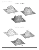
Page 67: ... offer Ultrasound The following diagrams show the typical spatial distribution of the radiated field for each size Dynatron 25 Series soundhead This applies to the radiation emitted into the equivalent of an infinite medium of distilled degassed water at 30 C and with line voltage variations in the range of 10 percent of the rated value 10 cm2 Head Near Field 3 MHz 1MHz 2 MHz ...

Page 68: ...Ultrasound Beam Profiles DYNATRON 25 SERIES OPERATOR S MANUAL 62 5 cm2 Head Near Field 2 cm2 Head Near Field 1MHz 2 MHz 3 MHz 1MHz 2 MHz 3 MHz ...

Page 69: ... hazard to the patient Use VERY LOW STIM INTENSITY for COMBO treatments Remember to observe all contraindications warnings precautions and usage cautions for BOTH Ultrasound and Electrical Stimulation therapy when performing combination therapy Since electrical current travels between the electrode and the soundhead during a COMBO treatment the electrode should be placed in proximity with the trea...

Page 70: ...he same time ultrasonic waves are introduced into patient tissue through the soundhead Avoid touching the electrode with the soundhead during the treatment keep the soundhead in contact with the patient s skin at all times and keep the intensity low for the Stim current In order to set up a COMBO treatment you must be familiar with setup instructions for both the electrotherapy modality to be used...

Page 71: ...l will change from WHITE to GREEN The SOUND channel will now be illuminated YELLOW Proceed to set up the STIM treatment following the modality instructions found in the manual Remember High Volt must use the designated HI VOLT Channel The system defaults to a PREMOD treatment selection unless another default therapy has been selected previously 7 Apply the conductive gel to the Ultrasound treatmen...

Page 72: ...h a Premodulated treatment and the respective default settings for those two modalities In COMBO mode you can save new default treatment time and the preferred Stim modality The Stim settings in a COMBO treatment are determined by the defaults of that modality Separate Ultrasound default settings may be saved for the COMBO treatment which will not affect Ultrasound only treatments If you save defa...

Page 73: ...annels the device will select a channel pair 1 2 or 3 4 Note Channels 3 4 are available on 25 Series 625 and 925 only Set Up A Second Treatment To set up the second or third treatment after you have set up and started the first modality press the modality key for the second treatment to be set up The device automatically selects the treatment channel s to be used The GREEN channel light shows you ...

Page 74: ...er RUNNING TREATMENTS is the active channel s illuminated in YELLOW and the name of the treatment modality with the remaining treatment time both illuminated in White To change the settings for a channel or output that has a YELLOW light press the CHANNELS toggle key one or more times until the light for the desired channel becomes GREEN The TIME and INTENSITY displays change to show the parameter...

Page 75: ... decrease swelling Implanted Electronic Devices Patients with Implanted Electronic Devices for example a cardiac pacemaker should not be subjected to stimulation Cardiac Conditions The electrodes should be placed to avoid the stellate ganglion and the heart itself If there is a potential for heart problems the clinician must exercise professional judgment and use adequate precautions The clinician...

Page 76: ...e Do not use over a carotid sinus Transcerebrally Disturbances in cardiac rhythm 6 The long term effects of chronic electrical stimulation are unknown 7 This device should not be used to relieve pain syndromes until etiology has been established 8 Current densities for any electrodes exceeding 2 mA r m s cm2 may require the special attention of the USER Precautions 1 Precautions should be observed...

Page 77: ...utlet or line with a whirlpool and certain traction machines In areas which are carpeted and static electricity is present it may be necessary to use a conductive mat or anti static carpet treatment to remove any static charge from the operator before touching the device 7 To avoid causing possible interference with the operation of the Dynatron device it should not be connected to anyone who is w...

Page 78: ...st their adhesiveness or carbon electrodes which are corroded and are not securely fastened fail to deliver current evenly as required These kinds of electrodes may have hot spots where higher than normal current density will be delivered If the patient complains of pin prick sensations the electrode may be delivering current through only a small portion of its area and the electrode should be rep...

Page 79: ...NS Pregnancy Acute and sub acute thrombosis and thrombophlebitis Potentially malignant lesions tumors malignant or benign Areas or lumps that may be suspected as cancerous or precancerous Third degree musculo tendonous lesions Cardiac pacemaker or other implanted electronic device Implants of any electrical nature Skin diseases Multiple sclerosis Osteomyelitis Disturbances in cardiac rhythm Tissue...

Page 80: ... stellate ganglion and subcutaneous major nerves To tissues previously treated by deep x ray or other radiation Over the joint capsule in acute or sub acute arthritic conditions Over ischemic tissue in patients with vascular disease Over a laminectomy site Over total joint replacements the effect of Ultrasound on the new plastics is unknown The Dynatron 25 Series Ultrasound should not be used over...

Page 81: ...hermy should not be turned on or used at the same time as this Dynatron device Do not use the same power outlet or line with a whirlpool and certain traction machines In areas which are carpeted and static electricity is present it may be necessary to use a conductive mat to remove any static charge from the operator Use a surge suppressor if power problems are encountered Avoid unnecessary exposu...

Page 82: ...ture Save New Defaults If your most common treatment settings are different than the ones already set for this device you can change the defaults to suit your own preferences Setting new defaults is simple and defaults may be changed again and again whenever needed 1 Press the modality key desired IFC Premod Russian Biphasic High Volt Micro Ultrasound or Combo 2 Set up a treatment using your prefe...

Page 83: ...have saved your own defaults but would like to return ALL the default settings to those that were set at the factory do the following 1 Turn the machine off and wait five seconds 2 Turn on the machine Following initialization DYNATRONICS appears in the Display Screen 3 Press and hold the START key down until three beeps are sounded The Factory Defaults have now been restored for all modalities You...

Page 84: ...TERY LEVEL GETTING LOW The treatment can continue however there will not be enough power to set up and deliver another treatment when the current treatment has ended 5 When the available battery power becomes too low to continue operating the device the following message will appear ERROR BATTERY LEVEL TOO LOW FOR TREATMENT OPERATION CHARGE IMMEDIATELY The treatment intensity will ramp down any tr...

Page 85: ...more power than Ultrasound or Stim modalities while Ultrasound requires more power than Stim modalities The intensity of the treatments The higher the intensity the higher the consumption of power The use of multiple treatments The more channels used the more power is consumed The amount of charge remaining on the battery As a general rule the unit may be run continuously for 30 minutes to several...

Page 86: ...Power Consumption 100 Watts Fuse 250V 1 6A slow blow Dimensions 18 5 W 41 91cm x 4 0 H 10 2cm x 12 0 D 30 5cm Weight 8 2 pounds 3 7 Kg Environmental Conditions Transport and Storage This equipment while packed for transport or storage should not be exposed to environmental conditions outside the following ranges a an ambient temperature range of 40 C b a relative humidity range of 10 to 100 includ...

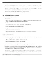
Page 87: ...onnected from a power source for service or otherwise Do not position the device such that it would be difficult to disconnect the power cord from the device Soundhead temperature monitoring prevents the soundhead from becoming too hot both to protect the soundhead crystal from damage and to ensure patient comfort Care and Cleaning Instructions 25 Series Console Clean the outer surface of the 25 S...

Page 88: ...on soundhead Verify DAC calibration and current limits It is recommended that the 25 Series device be sent to the manufacturer for annual calibration Maintenance Performed By User 1 Inspect accessories daily for wear and damage Examine cables and connectors on the cables for any visible sign of wear or damage Replace accessories as needed Replace lead wires and carbon electrodes at least every six...

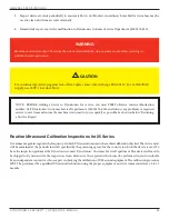
Page 89: ...atronics for the inspection As an alternative these periodic checks may be performed in your own locale by an independent contractor who is expert in checking the calibration of Ultrasound equipment The calibration procedure MUST be performed by a qualified Ultrasound technician using the proper equipment and is recommended every 6 to 12 months WARNING Hazardous electrical output To reduce the ris...

Page 90: ... a 3 to 4 second pause while the card syncs with the 25 Series system software A RED screen will appear with the following warnings DO NOT DISCONNECT POWER DO NOT TURN OFF 4 Press START to begin the download Follow the instructions on the screen 5 Remove the SD card from the SD CARD slot by gently pressing on the card Turn off the console 25 Series Software Update Screens NOTE All custom defaults ...

Page 91: ...ber of the unit 4 A description of the problem with the unit After receiving the Service Order Number SVO the number should be clearly written on the outside of the shipping container Packaging and Shipping of Replacement Parts All defective or broken parts should be shipped back to Dynatronics in the original shipping container These containers are designed to withstand the punishment of shipping...

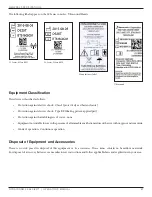
Page 92: ...nt Caution On Off power connection to the mains Type B patient applied part Type BF patient applied part Follow Instructions for Use Keep Dry Non ionizing Electromagnetic Radiation Made in USA Temperature Humidity Model Number Serial Number Fuse European Conformity Maintenance Battery Input Secure Digital Card Dynatronics Manufacturer Location Manufacturing Date Safety Certification for Canada and...

Page 93: ...n against harmful ingress of water none Equipment not suitable for use in the presence of a flammable anesthetic mixture with air or with oxygen or nitrous oxide Mode of operation Continuous operation Disposal of Equipment and Accessories There is no risk posed in disposal of this equipment or its accessories These items contain no hazardous materials For disposal of accessory batteries see manufa...

Page 94: ...the lead wire that is to be tested into the CH 1 output jack 2 Press the FUNCTION key on the right side of the User Interface board 3 Turn on the LEAD TEST function by toggling the 5th soft key under the right side of the LCD 4 Touch the two leads at the end of the cable together 5 The conductance bar will increase from left to right indicating the quality of the electrical conductance through the...

Page 95: ...ecked with the DMM This is done with the resistance setting of the meter Set the meter to Ohms Plug one of the test leads into the pin receptacle of the pad Touch the other lead to the black carbon surface of the pad If a resistance of more than 100 Ohms is seen the pad is beginning to break down and should be replaced ...

Page 96: ...quirements A graphical representation of typical output signals showing voltage waveforms at half and full setting of the output control when the EQUIPMENT is connected to resistive loads of 200 ohms 500 ohms 1000 ohms and 2000 ohms See the following pages for the graphical representations ...

Page 97: ...CAN CSA WaveformRequirements DYNATRON 25 SERIES OPERATOR S MANUAL 91 Interferential Current Mid Range Full Range 500 ohm Load 200 ohm Load 1000 ohm Load 2000 ohm Load ...

Page 98: ...CAN CSA WaveformRequirements DYNATRON 25 SERIES OPERATOR S MANUAL 92 Premodulated IFC Mid Range Full Range 500 ohm Load 200 ohm Load 1000 ohm Load 2000 ohm Load ...

Page 99: ...CAN CSA WaveformRequirements DYNATRON 25 SERIES OPERATOR S MANUAL 93 Russian Mid Range Full Range 500 ohm Load 200 ohm Load 1000 ohm Load 2000 ohm Load ...

Page 100: ...CAN CSA WaveformRequirements DYNATRON 25 SERIES OPERATOR S MANUAL 94 Biphasic Mid Range Full Range 500 ohm Load 200 ohm Load 1000 ohm Load 2000 ohm Load ...

Page 101: ...CAN CSA WaveformRequirements DYNATRON 25 SERIES OPERATOR S MANUAL 95 Hi Volt Mid Range Full Range 500 ohm Load 200 ohm Load 1000 ohm Load 2000 ohm Load ...

Page 102: ...atron 25 Series and accessories should assure that it is used in such an environment Emissions Test Compliance Electromagnetic Environment Guidance RF emissions CISPR 11 EN55011 Group 1 The Dynatron 25 Series and accessories uses RF en ergy only for its internal function Therefore its RF emis sions are very low and are not likely to cause any interfer ence in nearby electronic equipment RF emissio...

Page 103: ...hould be that of a typical commercial or hospital environment Surge IEC 61000 4 5 1 kV differential mode 2 kV common mode Compliant Mains power quality should be that of a typical commercial or hospital environment Voltage dips short interruptions and voltage variations on power supply input lines IEC 61000 4 11 5 Ut 95 dip in Ut for 0 5 cycle 40 Ut 60 dip in Ut for 5 cycles 70 Ut 30 dip in Ut for...

Page 104: ... meters m Field strengths from fixed RF transmitters as determined by an electromagnetic site survey should be less than the compliance level in each frequency range Interference may occur in the vicinity of equipment marked with the following symbol NOTE 1 At 80 MHz and 800 MHz the higher frequency range applies NOTE 2 These guidelines may not apply to all situations Electromagnetic propagation i...

Page 105: ...wer of the communications equipment Separation distance meters according to frequency of transmitter Rated maximum output power of transmitter W 150 kHz to 80 MHz d 1 17 x P 80 MHz to 800 MHz d 1 17 x P 800 MHz to 2 5 GHz d 2 33 x P 0 01 0 12 0 12 0 23 0 1 0 37 0 37 0 74 1 1 2 1 2 2 3 10 3 7 3 7 7 4 100 12 12 23 For transmitters at a maximum output power listed above the recommended separation dis...

Page 106: ...ests a probability that a device caused or contributed to a death serious injury or serious illness If you receive information that reasonably suggests a device malfunction and a recurrence will probably cause death serious injury or serious illness Definition of serious injury A serious injury is an injury that 1 is life threatening 2 results in permanent impairment of a body function or permanen...

Page 107: ...pection Make a note of treatment parameters that were in use during the treatment including intensity settings Also note environmental factors that were observed during the treatment office lights flickering static electricity discharge other devices in use on the same power source or in the same room etc The incident should be reported immediately to Dynatronics Customer Service at 1 800 874 6251...

Page 108: ...n freight prepaid fully insured and properly packed to prevent damage DYNATRONICS is not liable for any damage to the unit while in transit Include a summary of the problem with the product Write the return authorization number obtained from DYNATRONICS on the shipping label SHIPPING COSTS Within the first 30 days of the warranty period DYNATRONICS will pay all necessary shipping costs associated ...

Page 109: ...lure to register the warranty may result in a delay in completion of services and service will be billable How did you hear about the Dynatronics product you just purchased Check all that apply Decision to purchase your equipment was based on Check all that apply How do you find information about therapy products you want to purchase Check all that apply For information about therapy products what...

Reviews: