


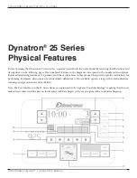


dynaTron® 25 serIes PhysICal feaTures
DYNATRON® 25 SERIES™ | OPERATOR’S MANUAL
11
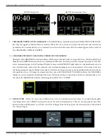
12. CONDUCTANCE/TEMPERATURE BAR
Conductance.
The 25 Series devices continuously measure conductance during electrical Stim treatments for Interferential, and
Premod to ensure that the treatment outcome is optimal and to minimize the possibility of patient discomfort due
to poor conductance and/or changes in current density. As conductance is measured, 25 Series displays the results
in graph form on the CONDUCTANCE bar located on the right side of the TREATMENT DISPLAY SCREEN.
Optimum conductance is displayed as the conductance bar flows RED - YELLOW- GREEN. GREEN indicating
the best CONDUCTANCE. If the green bar only partially fills the graph area, the conductance is at a percentage
of optimum. Lower INTENSITY may cause the bar to partially fill, but does not mean that the treatment is not
effective. Below are some helpful definitions.
Conductance and Worn Electrodes.
Conductance is how readily electrical current is passed from the electrode to the skin surface during a treatment.
Conductance affects current density. A worn electrode that does not conduct the current evenly over its entire
surface will have “hot spots” where a greater amount of current flows through a smaller area which means the
current density is higher at that point than elsewhere on the electrode. “Hot Spots” can lead to patient discomfort.
Never risk patient comfort by using worn electrodes or lead wires.
Intensity.
The intensity level is a convenient incremental measurement. However, raising the intensity increases the current
delivered to the patient but does not improve conductance.
Current Density.
Current density is the amount of current that passes through a given area of the electrode. Current density varies
depending on the size of the electrode, the conductance, and intensity setting; and has an effect on patient comfort.
With proper setup and good accessories, current is dispersed evenly over the entire surface of the electrode. The
smaller the electrode, the greater the density of the current delivered through the area. To reduce current density and
improve patient comfort, use larger electrodes, or lower the intensity setting, or both.
If the number of green displayed segments begin to decrease on the graph during a treatment, it is important to
determine the cause of the poor conductance. Remember with poor conductance you may inadvertently increase
current density at a small point under the electrode and cause patient discomfort. Following are some considerations
to insure proper conductance.
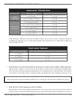
• Check to be sure electrodes are not worn or that self-adhesive electrodes have not lost their adhesiveness. These
are the most common causes of poor current delivery. Both self-adhesive and carbon electrodes eventually lose
their ability to conduct current effectively. See “Electrotherapy Usage Cautions” in this manual for recommended
intensity settings and usage limits.
• Check to ensure the entire surface of the poly adhesive electrode is adhering.
• Self-adhesive electrodes do not require sterilization, however, electrodes should be clean and hydrated (see
package instructions or “Self-Adhesive Electrodes” section of this manual).
• Check to be sure the snap adapters haven’t fallen off or that the lead wire has not become disconnected from the
electrodes or the device.
• Make sure carbon electrodes have a secure connection with the pin ends of the leads. Over time the carbon
electrodes may become too loose to use safely and the electrodes must be replaced.


