Dynacord CMS 1000-3 Owner'S Manual Download Page 56

CMS

3

56

2.3 FX 1/2

Das CMS ist mit zwei unabhängig voneinander regelbaren 24bit-Stereo-Effektteilen FX 1 und FX 2 aus-
gestattet. Die beiden Effektteile sind völlig identisch aufgebaut. Es stehen je Effektsektion 100 Presets 
zur Auswahl, die über das Display selektiert werden. Darüber hinaus besteht die Möglichkeit aus-
gehend von den Preset-Programmen einzelne Parameter der Effekte zu verändern und in 20 User-
Presets (Programmnummer 101-120) abzuspeichern. Näheres hierzu entnehmen Sie bitte dem 
Abschnitt Edit FX 1/FX 2 Menu auf Seite 67.
Die 100 Preset-Programme sind in Sektionen entsprechend der Effektstruktur eingeteilt. Die Pro-
gramme sind dabei so angeordnet, dass sie mit steigender Programmnummer innerhalb der jeweiligen 
Gruppe an Effekt-Intensität zunehmen. Auf den Plätzen 1-20 befinden sich High-Quality Reverbs die 
sowohl auf der Bühne sowie im Studio und Homerecording sehr gute Ergebnisse bringen. Mit den Pro-
grammnummern 21-40 stehen Echo+Reverb bzw. Chorus Mischprogramme zur Auswahl. An den Posi-
tionen 41-60 finden Sie unterschiedliche Delays und die Programmnummern 61-100 sind für 
Programme wie Doubling sowie spezielle Reverb und Delay-Programme reserviert. Die Effektteile wer-
den im fabrikneuen Zustand, beim Einschalten des Gerätes immer mit der voreingestellten Programm-
nummer 05 (BRIGHT HALL, Large Hall 3) für FX 1 und 55 (MONO DELAY, 230 ms 40%) für FX 2 starten. 
Diese Effekte sind auf der Bühne, beim Recording und auch beim gleichzeitigen Betrieb beider 
Effektteile sehr gut zu verwenden. Die Startprogramme können allerdings beliebig verändert werden, 
siehe Umstellung der Effekt-Startprogramme auf Seite 68.

Beachten Sie, dass die Tasten unter dem Display mit anderen Funktionen belegt werden, sobald Sie 
sich innerhalb der Menüs bewegen. Weitere Informationen entnehmen Sie bitte dem Abschnitt “DIS-
PLAY mit Funktions-Tasten” auf Seite 63.

A

USWAHL


EINES

 P

RESETS

Die Auswahl eines der Effektpresets gestaltet sich äußerst einfach: 
1.

Unterhalb der Preset-Nummernanzeige im Display sind den beiden Effektteilen jeweils zwei 
Tasten zugeordnet.

2.

Mit der DOWN-Taste (links) schalten Sie die Presets in absteigender Reihenfolge durch, mit der 
UP-Taste (rechts) in aufsteigender Reihenfolge.

3.

Wenn Sie länger auf eine dieser Tasten drücken, können Sie dadurch einen schnellen Vor- bzw. 
Rücklauf der Programmnummern erzeugen.

4.

Die Effektgruppen sind größtenteils in 10er-Schritten eingeteilt. Wenn Sie beide Tasten eines 
Effektteils gleichzeitig drücken, wird der erste Effekt der nächsten Effekt-Gruppe aufgerufen.

Beachten Sie bitte beim Testen und bei der Auswahl der Effekte in jedem Fall die Tabelle auf Seite 70. 
Hier sind alle Effektgruppen mit Namen, Effektstruktur, Einsatzgebiet und Klangcharakteristik aufgelis-
tet. Nehmen Sie sich Zeit, probieren Sie die unterschiedlichen Programme aus und entscheiden dann 
welches Programm für Ihre Anwendung am besten klingt.
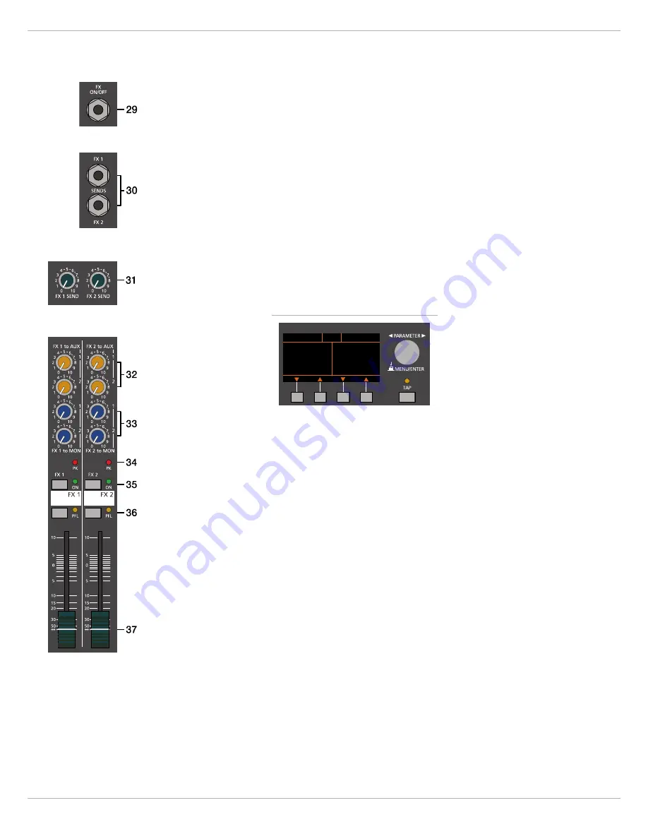
29 - FX ON/OFF-B

UCHSE

Die Klinkenbuchse FX ON/OFF dient zum Anschluss eines Fußschalters FS 11 (DC-FS11) aus dem Zu-
behörprogramm von DYNACORD. Die eingebauten Effektteile können damit ein- und ausgeschaltet 
werden. Zur Fernsteuerung mittels Fußschalter müssen die Effektgeräte über die FX 1 ON- bzw. FX 2 
ON-Schalter im Effektkanal aktiviert sein. 

HINWEIS:

Die Funktion des Fußschalters kann über den Eintrag Footswitch Ctrl. im FX Control 
Setup Dialog angepasst werden, siehe Seite 68.

Abbildung 2-16: Effekt-Betriebsart

BRIGHT HALL     MONO DELAY

REC STUDIO  MIDI  PEAK AUX 1

5     55

Large Hall 3     230 ms 40%

FX1            FX2

Summary of Contents for CMS 1000-3

Page 1: ...CMS3 CMS 1000 3 1600 3 2200 3 COMPACT MIXING SYSTEM Owner s Manual Bedienungsanleitung...

Page 2: ...CMS3 2...

Page 3: ...volution system 42 CMS mit VariLine System 43 SPECIFICATIONS 85 Dimensions 87 Block Diagram 88 INHALT EINF HRUNG 45 Lieferumfang Auspacken und berpr fen 45 Garantie 45 Aufstellen und Anschlie en 45 BE...

Page 4: ...cing to qualified service personnel 1 Security regulations as stated in the EN 60065 VDE 0860 IEC 65 and the CSA E65 94 have to be obeyed when servicing theappliance 2 Use of a mains separator transfo...

Page 5: ...company immediately if the CMS shows any damage Being the addressee you are the only person who can claim damages in transit Keep the cardboard box and all packaging materials for inspection by the t...

Page 6: ...l Because of the low impedance and the switchable PHANTOM POWER the XLR input is preferred for MIC applications Because of the high input acceptance of up to 21 dBu the XLR input is also suited to con...

Page 7: ...g offers the benefits of an improved S N ratio and provides you with the full bandwidth of the CMS s outstanding sound capabilities On the XLR type connectors an amplification of 0 dB is achieved when...

Page 8: ...ience will be thankful for the use of the LO CUT filter too since in this way they can enjoy a truly clear natural and powerful sound performance 6 VOICE FILTER This button activates an asymmetric mic...

Page 9: ...should try to avoid excessive enhancement Lowering the level more or less in this band will provide you with high amplification rates without feedback Use the LO control according to your pleasing to...

Page 10: ...ader s setting This mode is mainly used for monitoring Pre Fader Monitoring is espe cially preferable when monitoring and master mix need to be completely different from each other e g when the volume...

Page 11: ...r lights continuously the corresponding channel is likely to enter clipping and you have to turn the gain control a bit to the left The Signal LED lights at levels 30 dB below clipping while the peak...

Page 12: ...ly suitable for connecting Line level appliances like mix ers effects units etc Please use the provided LINE inputs to connect those sound sources General functions and usage of MIC inputs were alread...

Page 13: ...ed to the audio signal of the corresponding LINE input which could lead to unnecessary extra noise at the master output becoming clearly intelligible in pro gram breaks 19 GAIN LINE CD USB These rotar...

Page 14: ...of that specific frequency band Before you begin to alter the sound all EQ controls should be set to their neutral position i e their marker points straight up locked in place Do not set the EQ contr...

Page 15: ...ontrols and the channel fader 26 PFL Engaging the PFL button sums the stereophonic audio signal of the corresponding input channel and routes the result ing monaural signal to the headphones bus You a...

Page 16: ...the number of the active preset Use the UP button right of an effect unit to increase the number of the active preset 3 Keeping a button pressed continuously lets you step quickly through the program...

Page 17: ...trol to add the effect mix to the AUX or monitor mix Use the Effekt Return fad ers to add the desired amount of the FX signal to the master mix In case you are using a different effect setting for the...

Page 18: ...ultaneously switched so that the left LED chain indicates the level of the actually chosen channel in dBu leaving you with the opportunity for adjusting the level without routing it to the AUX 1 2 SEN...

Page 19: ...where feedback starts The slightly hovering sound that you hear is generated by the system itself Switch on the feedback filter turn the rotary control and set it at the mark where the sound disappear...

Page 20: ...that the left LED chain indicates the level of the summed pre fader L R master signal channel in dBu which basically is the master bus level while the right LED indicates the level of the summed post...

Page 21: ...evel via master fader makes sense when using an active subwoofer For monitoring ap plications e g side fill on the stage using the pre fader setting seems more reasonable 59 STEREO MONO OF MASTER B Wh...

Page 22: ...source the out putted level can instantly hit the top 65 REC SEND USB OUT This control allows adjusting the volume at the REC SEND outputs or when used the level of the DIGITAL AUDIO INTERFACE output...

Page 23: ...2 LED lights green The latter is espe cially useful if similar monitor speakers are used for both monitor channels Please see page 27 for changing the Graphic EQ Routing 2 7 DISPLAY with function keys...

Page 24: ...cord 74 POWER Mains switch to turn the CMS on or off The CMS is operational when the display indicates the selected program num bers Please make sure to set the master faders to their minimum position...

Page 25: ...indicates the func tion for the four function keys The following table de scribes some of the functions avialable in menu dialogs Illustration 3 1 Effect mode BRIGHT HALL MONO DELAY REC STUDIO MIDI P...

Page 26: ...MENU ENTER rotary encoder to select the user preset where the edited effect should be stored to Press the MENU ENTER rotary encoder to open the Set FX Name dialog Illustration 3 5 Menu structure of CM...

Page 27: ...r to highlight an en try in the left column of the FX Control Setup dialog Press the MENU ENTER rotary encoder to select the cor responding value in the right column Now turn the MENU ENTER rotary enc...

Page 28: ...to effect mode Show Device Name The indication of the Device Name instead of the status indications in the top line of the display in effect mode can be activated or deactivated Press the MENU ENTER...

Page 29: ...h fading echo organ guitar strings 40 Flanger real late sixties jet flanger drums prcussion bass strings vocals 41 50 Stereo Delay L R echoes combined with a reverb effect well suited for vocals horns...

Page 30: ...e PC or CMS3 app Mac found in the root directory of the DVD 4 Select the language of the application 5 Start installation of the USB driver for your opera ting system by clicking the corresponding but...

Page 31: ...from your PC to the CMS open the Sounds and Audio Devices Prop erties in the Windows Control Panel Select DYNACORD USB MIDI as Default Device for MIDI music playback Illustration 4 2 DIGITAL AUDIO INT...

Page 32: ...e routed bypassing the STANDBY switch to the 2TRACK IN control This function can be activated under the menu item Play USB to 2TRACK of the Device Setup Menu see also page 28 HINT Keep in mind that th...

Page 33: ...n the PC A very convenient option to accomplish this is to assign the stereo master of your software application to the playback channels USB 1 and USB2 of the CMS In order to gain the full flexibilit...

Page 34: ...the faders you can comfortably adjust the volume level as if you had connected a key board with built in tone generator to the stereo line in puts The CMS offers similar options for the creation of s...

Page 35: ...unction with the common mode rejection of the CMS s input stage effectively elim inates even existing artifacts of interference All inputs of the CMS provide balanced audio connections and high common...

Page 36: ...he corresponding PHANTOM POWER switch 11 Activate the CMS s operational mode through pressing the STANDBY switch again 5 3 Soundcheck First adjust the input levels of the microphones that are connecte...

Page 37: ...hat you don t use the CMS as FOH mixer in the audience area but on stage The following procedure is explained for MON 1 For setting MON 2 please perform the same steps analogous 1 Lower the setting of...

Page 38: ...CMS3 38 6 Setup examples 6 1 CMS with D Lite activeone Illustration 6 1 CMS with D Lite activeone 2 x D 8A 1 x PowerSub 212 as main PA 2 x D 8A used as monitors COMPACT MIXING SYSTEM CMS 1000...

Page 39: ...CMS3 39 6 2 CMS with D Lite activetwo Illustration 6 2 CMS with D Lite activetwo 2 x D 8A 2 x PowerSub 112 as main PA 2 x D 8A used as monitors COMPACT MIXING SYSTEM CMS 1000...

Page 40: ...CMS3 40 6 3 CMS with D Lite activefour Illustration 6 3 CMS with D Lite activefour 2 x D 11A 2 x PowerSub 212 as main PA 2 x D 11A used as monitors COMPACT MIXING SYSTEM CMS 1000...

Page 41: ...CMS3 41 6 4 CMS with Xa 2 system Illustration 6 4 CMS with Xa 2 system 2 x FX 12 4 x FX20 2 x Xa 4000 as main PA 2 x D 8A used as monitors COMPACT MIXING SYSTEM CMS 1000 Xa 4000 Xa 4000...

Page 42: ...ith CORUS Evolution system Illustration 6 5 CMS with CORUS Evolution system 2 x C 25 2 2 x Sub 2 18 2 x LX 3000 1 x DSP 260 as main PA 2 x D 11A used as monitors COMPACT MIXING SYSTEM CMS 1000 DSP 260...

Page 43: ...ine System Illustration 6 6 CMS with VariLine system 2 x VL 152 2 x Sub 18 3 x LX 3000 1 x DSP 600 as main PA 2 x VL 122 and 1 x LX 2200 used as monitors COMPACT MIXING SYSTEM CMS 1000 DSP 600 LX 3000...

Page 44: ...nweise sind ausschlie lich zur Verwendung durch qualifiziertes Servicepersonal Um die Gefahr eines elektrischen Schlages zu vermeiden f hren Sie keine Wartungsarbeiten durch die nicht in der Bedienung...

Page 45: ...ransportschaden kann nur von Ihnen dem Empf nger reklamiert werden Bewahren Sie den Karton und das Verpackungsmaterial zwecks Be sichtigung durch das Transportunternehmen auf Die Aufbewahrung des Kart...

Page 46: ...ng und die M glichkeit der Phantomspannungs Aufschaltung ist der XLR Eingang wesentlich f r Mikrofonanwendungen aus gelegt Durch die hohe Pegelfestigkeit bis 21 dBu ist er aber ebenso geeignet f r den...

Page 47: ...en internen Arbeitspegel des Mischpultes angepasst werden Durch eine gewissenhafte Einpegelung des Signals k nnen Sie den Signal Rauschabstand optimieren und die hervorragenden Audioeigenschaften des...

Page 48: ...tieffrequenten St rsignalen beaufschlagt werden die nur die Anlage dicht machen und an denen weder Sie noch ihr Publikum interessiert sind Ihre Lautsprecherboxen werden Ihnen die Ver wendung des LO CU...

Page 49: ...timalen Arbeitsfrequenz mit dem Frequenzsteller nicht immer ganz einfach gestaltet Darum hier eine M glichkeit unter vielen wie Sie schnell eine f r Ihre Anwendung passende Einstellung des parametrisc...

Page 50: ...den AUX 1 2 Fader im Master eingestellt Beachten Sie aber dass ein Aufziehen eines Kanalfaders sich auf den Monitormix auswirkt und bei unbedachter Bedienung eine erhebliche R ckkopplungsgefahr beste...

Page 51: ...zutr glich ist 15 FADER Mit dem Kanalschieberegler Fader wird die Lautst rkeeinstellung des Einzelkanals vorgenommen und die Lautst r kebalance der einzelnen Eingangskan le untereinander eingestellt D...

Page 52: ...ten usw Benutzen Sie hierf r bitte die vorgesehenen LINE Eing nge Die gene relle Funktionsweise oder Verwendung eines MIC Inputs haben Sie bereits im Monokanal kennengelernt 17 STEREO INPUT L MONO R...

Page 53: ...pfindlichkeit der MIC Eing nge im Stereokanal wodurch die ankommenden Signale optimal auf den internen Arbeitspegel des Mischpultes angepasst werden k nnen Der GAIN MIC Regler bedient im Ste reokanal...

Page 54: ...Jeder Eingang besitzt seinen eigenen GAIN MIC bzw GAIN LINE CD USB Regler Sie k nnen also bei diesem Eingangskanal zus tzlich zum Mikrofon eine Line Quelle anschlie en Beide Quellen nutzen dann aber a...

Page 55: ...N Regler und des Faders ndern zu m ssen 26 PFL SCHALTER Dieser Schalter gibt das Stereo Signal summiert als Monosignal auf die Kopfh rersumme Sie k nnen damit das Eingangssignal am Kopfh rerausgang PH...

Page 56: ...achten Sie dass die Tasten unter dem Display mit anderen Funktionen belegt werden sobald Sie sich innerhalb der Men s bewegen Weitere Informationen entnehmen Sie bitte dem Abschnitt DIS PLAY mit Funkt...

Page 57: ...oweit auf oder zu bis die Lautst rke der Effektzumischung Ihren Vorstellungen entspricht Wiederholen Sie diesen Punkt f r alle Eingangskan le die Sie mit einem Effektsignal beaufschlagen wollen 6 Stel...

Page 58: ...t dabei unabh ngig vom AUX Fader Pre Fader Listen Gleichzeitig bewirkt das Dr cken des PFL Schalters ein Umschalten der Aussteuerungsanzeigen im Master Die linke LED Kette zeigt dabei den Pegel in dBu...

Page 59: ...neigt Gehen Sie dabei folgenderma en vor Als erstes erh hen Sie vorsichtig die MON 1 2 Lautst rke bis an die R ckkopplungsgrenze Es beginnt sich ein leicht schwebender Ton auszupr gen den die Anlage...

Page 60: ...ader Gleichzeitig bewirkt das Dr cken des PFL Schalters ein Umschalten der Aussteuerungsanzeigen im Master Die linke LED Ket te zeigt dabei den internen Pegel des Masterbusses in dBu an 52 MASTER L R...

Page 61: ...B Bei Wahl von PRE ist der Pegel am MASTER B Ausgang unabh ngig von der Einstellung der MASTER L R Fader und falls verwendet des Graphic Equalizers Bei Wahl von POST ist der Pegel am MASTER B Ausgang...

Page 62: ...ingangskan le sind in Bezug auf den Hauptausgang stummgeschalten aber das 2TRACK IN Signal kann trotzdem ungehindert passieren HINWEIS Das 2TRACK IN Signal ist auf folgenden Ausg ngen nicht verf gbar...

Page 63: ...n auf ein breiteres Frequenzband eingewirkt wird als bei starken Eingriffen bei denen man in der Regel gezielt einzelne Frequenzen beeinflussen m chte um z B R ckkopplungen zu bek mpfen Sollten Sie al...

Page 64: ...ay aktiv kann die Delay Zeit durch Bet tigung der TAP Taste dem Takt der Musik angepasst werden Die gelbe LED blinkt entsprechend der aktuellen Delay Zeit Bitte beachten Sie zur Funktion der TAP Taste...

Page 65: ...Schieberegler geschlossen sind oder der STANDBY Schalter gedr ckt ist Sie ersparen sich selbst Ihrem Publikum und Ihrem Equipment unn tige Beanspru chungen durch ungewollte Signalverst rkung oder sog...

Page 66: ...n bernommen Die unterste Zeile im Display zeigt f r die vier Funktion stasten stets die Funktion an die bei Bet tigung der Tas te ausgef hrt wird Folgende Tabelle erl utert einige der in den verschied...

Page 67: ...en Sie die SAVE Funktionstaste der FX User Presets Dialog er scheint W hlen Sie im FX User Presets Dialog den gew nschten Speicherplatz durch Drehen des MENU ENTER Drehencoders Dr cken des MENU ENTER...

Page 68: ...FX Control Setup Dialog erlaubt die Konfiguration der Effektteile FX 1 bzw FX 2 des CMS Bestimmte Eigen schaften der Effektteile k nnen ber die MIDI Schnitt stelle bedient werden Zus tzlich k nnen in...

Page 69: ...e dort eingestellte Bezeichnung wird nach dem Einschalten des Ger ts im Display ange zeigt Die Bezeichnung kann maximal 18 Zeichen lang sein es stehen die Zeichen A Z a z 0 9 und mehrere Son derzeiche...

Page 70: ...ndung 01 10 Bright Hall Nachhall mit brillanter Klangcharakteristik Konzertsaal Kirche Kathedrale Vocals Bl ser Strings 11 20 Bright Plate Plattenhall mit brillanter Klangcharakteristik ohne wahrnehmb...

Page 71: ...n Sie im Startbildschirm die gew nschte Sprache f r die Anwendung aus 5 Starten Sie die Installation des f r Ihr Betriebssys tem passenden USB Treibers durch Klick auf den entsprechenden Button HINWEI...

Page 72: ...en an den PC bermittelt werden Eine Fehlinterpretation der Daten l sst sich durch eine geeignete Auswahl der MIDI Kan le vermeiden beachten Sie hierzu Abschnitt FX Control Setup auf Seite 68 und die D...

Page 73: ...stallation wird automa tisch auch der ASIO Treiber mitinstalliert Zur Zuweisung der Ausspielwege auf die Wiedergabekan le des CMS beachten Sie die Dokumentation der von Ihnen ver wendeten Software PLA...

Page 74: ...fon getrennt voneinander aufzunehmen Bei der Nachbearbeitung der Aufnahmen k nnen Sie die beiden Anteile im optimalen Verh ltnis aufeinander abstimmen HINWEIS Beachten Sie dass bei der Aufnahme die Si...

Page 75: ...ang enthaltenen Cubase LE werden dann Kl nge er zeugt Durch die Leistungsf higkeit heutiger Laptops ist es kein Problem mehr Ihre Klangpalette auch im Live Einsatz um Sounds zu erweitern die vor wenig...

Page 76: ...alen im wesentlichen Brummen auf den Audiosi gnalpfad Ferner werden Rest Einstreuungen durch die symmetrische Leitungsf hrung in Verbindung mit der Gleichtaktunterdr ckung der Eingangsstufe wirkungsvo...

Page 77: ...schieberegler schlie en 2 Sprechen oder singen Sie mit der maximal zu erwartenden Lautst rke in das Mikrofon 3 Gleichen Sie dabei mit dem Gain Regler den Pegel so ab dass auch bei sehr lauten Passagen...

Page 78: ...Bedarf die Punkte 1 bis 6 auch f r das zweite Effektteil FX 2 durch MONITORMIX Die Vorgehensweise zur Erstellung des Monitormix ist nachfolgend f r MON 1 gezeigt und ist nat rlich f r MON 2 identisch...

Page 79: ...S3 79 6 Aufbaubeispiele 6 1 CMS mit D Lite activeone Abbildung 6 1 CMS mit D Lite activeone 2 x D 8A 1 x PowerSub 212 als Haupt PA zus tzlich 2 x D 8A f r die Monitorwege COMPACT MIXING SYSTEM CMS 100...

Page 80: ...CMS3 80 6 2 CMS mit D Lite activetwo Abbildung 6 2 CMS mit D Lite activetwo 2 x D 8A 2 x PowerSub 112 als Haupt PA zus tzlich 2 x D 8A f r die Monitorwege COMPACT MIXING SYSTEM CMS 1000...

Page 81: ...CMS3 81 6 3 CMS mit D Lite activefour Abbildung 6 3 CMS mit D Lite activefour 2 x D 11A 2 x PowerSub 212 als Haupt PA zus tzlich 2 x D 11A f r die Monitorwege COMPACT MIXING SYSTEM CMS 1000...

Page 82: ...CMS3 82 6 4 CMS mit Xa 2 System Abbildung 6 4 CMS mit Xa 2 System 2 x FX 12 4 x FX20 2 x Xa 4000 als Haupt PA zus tzlich 2 x D 8A f r die Monitorwege COMPACT MIXING SYSTEM CMS 1000 Xa 4000 Xa 4000...

Page 83: ...RUS Evolution System Abbildung 6 5 CMS mit CORUS Evolution System 2 x C 25 2 2 x Sub 2 18 2 x LX 3000 1 x DSP 260 als Haupt PA zus tzlich 2 x D 11A f r die Monitorwege COMPACT MIXING SYSTEM CMS 1000 D...

Page 84: ...stem Abbildung 6 6 CMS mit VariLine System 2 x VL 152 2 x Sub 18 3 x LX 3000 1 x DSP 600 als Haupt PA zus tzlich 2 x VL 122 und 1 x LX 2200 f r die Monitorwege COMPACT MIXING SYSTEM CMS 1000 DSP 600 L...

Page 85: ...her inputs 22 dBu All other outputs 22 dBu Input Impedances MIC 2 kOhms Insert Return 3 3 kOhms 2Track Return CD In 10 kOhms All other inputs 15 kOhms Output Impedances Phones 47 Ohms All other output...

Page 86: ...ps 48 V DC Power Requirements SMPS with auto range mains input 100 V to 240 V AC 50 Hz to 60 Hz Safety Class I Ambient Temperature Limits 5 C to 40 C 40 F to 105 F Dimensions W x H x D without lid mm...

Page 87: ...CMS3 87 7 1 Dimensions...

Page 88: ...CMS3 88 7 2 Block Diagram...

Page 89: ...ountries Apple Macintosh Mac OS and Mac OS X are trademarks of Apple Inc registered in the United States and other countries Cubase is a registered trademark of Steinberg Media Technologies GmbH ASIO...

Page 90: ...CMS3 90 Notes...

Page 91: ...CMS3 91 Notes...

Page 92: ...844 4051 Fax 1 952 884 0043 49 9421 706 0 Fax 49 9421 706 265 Asia Pacific only For customer orders contact Customer Service at www dynacord com 65 6571 2534 Fax 65 6571 2699 For technical assistance...

Reviews: