DynaColor QIG-510 Series Installation Manual Download Page 46

Installation Guide 


45

4) 

Attach the Waterproof Rubber to the Standard/ Compact Pendent Mount. 

5) 

Thread the cable(s) through the Indoor Mount Kit and join the Indoor 
Mount Kit to the Standard/ Compact Pendent Mount with the supplied 
screws and washers. Then adjust the Waterproof Rubber to the joint. 

6) 

Connect the cable(s) to the Dome Camera. 

7) 

Join the Dome Camera to the Indoor Mount Kit with the supplied screw 
and washers. 

 
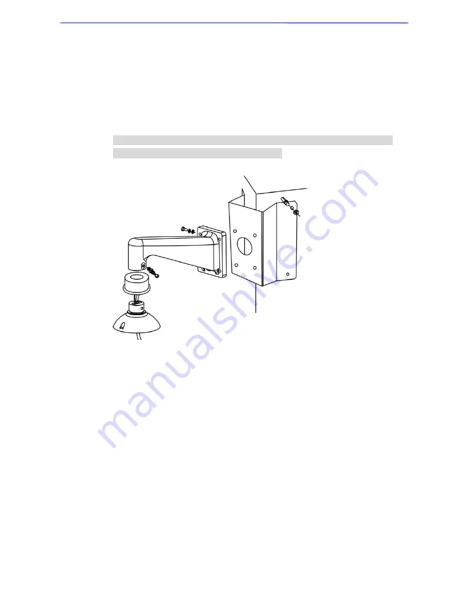
Corner Wall Mounting: Corner Standard/Mini Mounting Plate + Standard/ 
Compact Pendent Mount + Indoor Mount Kit 


Summary of Contents for QIG-510 Series

Page 1: ...00P6H510CZXSEA6 Mini Speed Dome Camera Indoor Dome Camera Installation Guide Version 1 6...

Page 2: ...er manual may not be copied photocopied translated reproduced or reduced to any electronic medium or machine readable format in whole or in part without prior written permission of the company Importa...

Page 3: ...vironment and human health which could otherwise be caused if this product is thrown into the garbage bin The recycling of materials will help to conserve natural resources For more details informatio...

Page 4: ...side Blocking the cooling holes leads to build up of heat the camera and may cause malfunction Do not operate the camera beyond the specified temperature humidity or power source ratings Use the indoo...

Page 5: ...Never face the camera towards the sun Do not aim the camera at bright objects Whether the camera is in use or not never aim it at the sun or other extremely bright objects Otherwise the camera may be...

Page 6: ...n 19 4 1 Camera Dimensions 19 4 2 Optional Accessories 20 4 3 Ceiling Mount 27 4 3 1 Hard Ceiling Mount 27 4 3 2 In Ceiling T Bar Mounting 31 4 3 3 Straight Tube 34 4 4 Wall Mount 37 4 4 1 Swan Tube 3...

Page 7: ...Installation Guide 6 Appendix A Technical Specification 57...

Page 8: ...PC The Mini Dome Cameras contain a built in receiver that decodes commands originating from a control device Connect Dome Cameras to other devices as shown in the diagram to complete a video surveilla...

Page 9: ...amage is evident DO NOT install or operate the product and contact your dealer for assistance Analog Model Dome Camera Data Cable for Power Supply Video and Audio DC 12V Power Adaptor Power Cord DC mo...

Page 10: ...Camera Data Cable for Power Supply Video and Audio DC 12V Power Adaptor Power Cord DC model only Data Cable for Power Supply Video and Audio AC 24V Hard Ceiling Mount Decoration Ring M3 Screw Fixing...

Page 11: ...a Additionally the 22 Pin Connector for Data Cable connection and ISP Connector for firmware upgrade kit connection are located on the back plate of both analog and network Speed Dome Cameras 3 1 1 Sw...

Page 12: ...S 485 Setting SW 3 Termination SW 4 Line Lock SW 5 Factory Default Reset SW 6 Camera Upgrade RS 485 is the interface that communicates the Dome Camera and its control device for this reason the RS 485...

Page 13: ...peed Dome Camera s ID by setting the 10 bit dip switch For instance if the camera s ID is 006 set the SW 8 and SW 9 to ON with the rest to OFF as shown below For switch configuration details please re...

Page 14: ...00 VCL 9600 01 Pelco D 2400 02 Pelco P 4800 04 Chiper 9600 05 Philips 9600 07 DSCP 9600 08 AD422 4800 09 DM P 9600 11 Pelco D 4800 12 Pelco D 9600 13 Pelco P 2400 14 Pelco P 9600 15 JVC 9600 21 Kalate...

Page 15: ...ed below The video cable sends video signals to a remote viewing site Using a coaxial cable to send video signals is recommended RS 485 cable carries commands from a control device to the Dome Cameras...

Page 16: ...k Network Model The network Speed Dome Camera s Data Cables are illustrated as shown below AC 24V Data Cable DC 12V Data Cable 3 2 3 22 Pin Connector Definition With the 22 pin connector installers ca...

Page 17: ...LM 6 7 T 18 ALM 7 8 R 19 ALM 8 9 T 20 ALM GND 10 R 24AWG 21 VGND 11 ISOG 22 Video 20AWG Network Model The network Speed Dome Camera s 22 pin connector definition is listed below Pin Definition Cable P...

Page 18: ...s recommended Please refer to the figure and table below for pin defination and wiring 3 2 5 Cable Wiring and Connection Users may need to conduct cable wiring when 1 Connecting self provided cords to...

Page 19: ...n the back plate of the Dome Camera NOTE The figure on the right side is for illustration only Please refer to section 3 1 1 Switch Definition for correct back plate layout 3 2 6 Ethernet Cable Connec...

Page 20: ...accessories installation methods and installation procedures will be described in detail The next section will provide the Dome Camera s dimensions for your reference before installation 4 1 Camera Di...

Page 21: ...ring make sure the Ground wire inserted into the mid pin of the terminal block Mounting Accessories Indoor Mount Kit For mounting the indoor Dome Camera onto a Standard Pendent Mount Straight Tube Whi...

Page 22: ...d ceiling sticker x1 Standard Pendent Mount White 348 104 138 6 mm 13 7 4 1 5 5 inches 1 5 kg 3 3 lbs Diameter 45 mm 1 8 inches Supplied with M8x12 screw x1 spring washer 8 x1 pendent tube washer x1 r...

Page 23: ...rubber x1 Swan Tube For mounting with Swan Tube White Iron Dimension 835 x 300 mm 32 9 11 8 inches Diameter 45 mm 1 8 inches Weight 3 8 kg 8 4 lbs Supplied with pendent tube washer x1 rubber washer 8...

Page 24: ...washer 8 x4 M8x16 screw x4 and M8 nut x4 Corner Thin Box Mounting White Ivory 300 164 222 mm 11 8 6 5 8 7 inches 3 kg 6 7 lbs Supplied with M8x16 screw x4 washer 8 x4 and spring washer 8 x4 Corner Wid...

Page 25: ...washer x4 and stainless steel straps x4 Pole Wide Box Mounting White Ivory 270 166 155 mm 10 6 6 5 6 1 inches 3 2 kg 7 1 lbs Supplied with M8x16 screw x4 washer 8 x4 spring washer 8 x4 and stainless s...

Page 26: ...ect Mounting White Ivory 270 170 60 mm 10 6 6 7 2 4 inches Diameter 112 130 mm 4 4 5 inches 1 kg 2 2 lbs Supplied with M8x16 screw x4 washer x4 stainless steel straps x4 spring washer 8 x4 Stainless S...

Page 27: ...D77R2 D77R3 Connector Box Indoor Application Recommended for wiring indoor dome alarm cables White Color 92 42 mm 3 7 1 7 inches 0 13 kg 0 3 lbs Supplied with cable 1 bracket 1 and M3x6 screw 2 Signal...

Page 28: ...items and tools needed for hard ceiling installation are listed as follows all the supplied items are available in the Dome Camera s standard package Items Needed Dome Camera Data Cable supplied Ethe...

Page 29: ...e holes on the Fixing Plate to the ones on the back plate and then screw the Fixing Plate tightly using the supplied M3 screw NOTE The orientation of the Fixing Plate is shown in the figure on the rig...

Page 30: ...to the Dome Camera s corresponding connector NOTE If use the network Speed Dome Camera an Ethernet cable is needed other than the Data Cable STEP 8 Attach the Dome Camera to the Mount and rotate it c...

Page 31: ...the figure STEP10 Assemble the Decoration Ring to the Mount by pushing it up through the camera body and aligning the three pillar like fasteners to the corresponding holes of the Decoration Ring STEP...

Page 32: ...er x1 Items Needed Dome Camera Data Cable M3 screws 2 supplied Ethernet Cable network Dome Camera In Ceiling T Bar Mount Kit In Ceiling T Bar Mount Lock Bar Ceiling Sticker optional accessory Tools Ne...

Page 33: ...ling Sticker onto the ceiling and cut the circle part Diameter 162 mm out of the ceiling STEP 3 Hold up the In Ceiling T Bar Mount and put it into the opening STEP 4 Tighten the three fixing screws on...

Page 34: ...with the board NOTE Please make sure the In Ceiling Mount s wings are completely flush with the ceiling board STEP 6 Run the Data Cable through the center hole of the In Ceiling Mount Then Connect th...

Page 35: ...te the camera clockwise and let the screw hole on the Lock Bar align with the fixing screw hole on the In Ceiling Mount s ring STEP 8 Screw the Dome Camera onto the In Ceiling Mount with the supplied...

Page 36: ...ke a cable entry hole on the ceiling 3 Fix the Straight Tube to the ceiling with proper screws and screw anchors 4 Attach the Waterproof Rubber to the Straight Tube 5 Run the cable s through the Strai...

Page 37: ...Installation Guide 36 Ceiling Mount Straight Tube Indoor Mount Kit...

Page 38: ...oof Rubber standard accessory Screws and Screw Anchors for fixing the Swan Tube on the floor not supplied Tools Needed Tool for drilling Tool for screwing Follow the steps to mount the dome with the S...

Page 39: ...x1 M8x12 Screw x1 Items Needed Dome Camera Data Cable supplied Ethernet Cable network Dome Camera Compact Pendent Mount and equipped items optional accessory Indoor Mount Kit optional accessory Water...

Page 40: ...the cable s through the Compact Pendent Mount with the Data Cable s 22 pin cable coming out of the outlet NOTE Please block the cable entry hole with the supplied sponge to avoid insects entering the...

Page 41: ...amera Data Cable supplied Ethernet Cable network Dome Camera Standard Pendent Mount and equipped items optional accessory Indoor Mount Kit optional accessory Waterproof Rubber Indoor Mount Kit s acces...

Page 42: ...the Standard Pendent Mount with the Data Cable s 22 pin cable coming out of the outlet NOTE Please block the cable entry hole with the supplied sponge to avoid insects entering the Pendent Mount See...

Page 43: ...ard Compact Pendent Mount and Wall Box Mounting 1 Make a cable entry hole on the wall to recess the cable s 2 Fix the Wall Box Mounting on the wall with proper screws and screw anchors Then run the ca...

Page 44: ...d Compact Pendent Mount with the supplied screws and washers Then adjust the Waterproof Rubber to the joint 6 Connect the cable s to the Dome Camera 7 Join the Dome Camera to the Indoor Mount Kit with...

Page 45: ...ling Tool for screwing Follow the steps below to mount the Dome Camera with the Corner Mounting Plate and Standard Compact Pendent Mount 1 Make a cable entry hole on the wall to recess the cable s 2 F...

Page 46: ...Mount Kit to the Standard Compact Pendent Mount with the supplied screws and washers Then adjust the Waterproof Rubber to the joint 6 Connect the cable s to the Dome Camera 7 Join the Dome Camera to t...

Page 47: ...n the wall to recess the cable s 2 Fix the Corner Thin Wide Box on the corner of the wall with proper screws and screw anchors Then run the cable s through the hole on the Corner Mounting Plate with t...

Page 48: ...st the Waterproof Rubber to the joint 6 Connect the cable s to the Dome Camera 7 Join the Dome Camera to the Indoor Mount Kit with the supplied screw and washers Corner Box Mounting Corner Thin Wide B...

Page 49: ...Tool for screwing Follow the steps below to mount the Dome Camera with the Pole Thin Wide Direct Mounting and Standard Compact Pendent Mount 1 Fasten the Pole Thin Wide Direct Mounting on a pole with...

Page 50: ...or Mount Kit to the Standard Compact Pendent Mount with the supplied screws and washers Then adjust the Waterproof Rubber to the joint 6 Connect the cable s to the Dome Camera 7 Join the Dome Camera t...

Page 51: ...tandard Compact Pendent Mount 1 Fasten the Pole Thin Wide Box on a pole with equipped stainless straps 2 Run the cable s through the hole on the Pole Thin Wide Box Mounting with the Data Cable s 22 pi...

Page 52: ...just the Waterproof Rubber to the joint 6 Connect the cable s to the Dome Camera 7 Join the Dome Camera to the Indoor Mount Kit with the supplied screw and washers Pole Box Mounting Pole Thin Wide Box...

Page 53: ...r devices for easy installation To connect the connector box with other devices Use a RS 485 cable CAT 5 is recommended to complete RS 485 communication wiring with control devices such as DVRs and Co...

Page 54: ...between devices If a converter repeater is used the total network distance of the surveillance system can be extended and the connected devices will also be protected Up to 10 devices are allowed to...

Page 55: ...ng with cameras up to 1 0 kilometers away Additionally the SDU can be installed in either star or daisy chain configuration with up to 160 cameras see the diagrams below Its versatile installation con...

Page 56: ...n Set Preset Number key press and hold Preset button for three seonds Go Preset Number key Preset to command a dome camera to go to a specific preset position Display or hide an OSD menu 7 7 Preset Mo...

Page 57: ...set position set Set preset position Special Function 7 6 set Exit the OSD menu directly 7 7 set 1 Display or hide the OSD menu 2 A virtual key to issue an ENTER command when the OSD is displayed 7 8...

Page 58: ...Outdoor Iris Control Auto Manual Electronic Shutter 1 1 1 10k sec AGC control Auto Manual Back Light Compensation On Off OPERATION Built in Protocol DynaColor Pelco D P VCL Philips AD 422 JVC etc Mult...

Page 59: ...3D On Off Alarm Input 8 Alarm Output 1 Alarm Reaction Preset Sequence Auto pan Cruise GENERAL Environment Indoor Controller Interface RS 485 Operating Temperature 0 C 40 C 32 F 104 F Dimension 131 x 2...

Reviews: