background image

Maintenance Manual (960-948)

3-14

Tests and Diagnostics

The PC will restart. Press 

F12

 and select the USB memory as the boot 

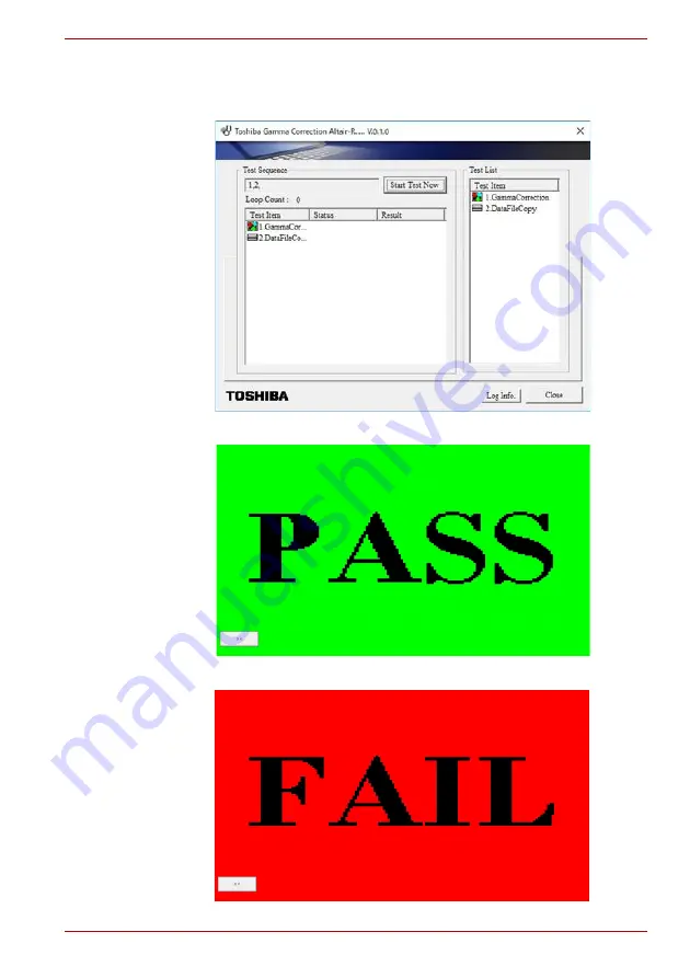
device. Then the following screen will appear and the correction is done 

automatically.

If this program ends successfully, “PASS” is displayed.

If any errors occurred, “FAIL” will be displayed.

Summary of Contents for Portege X30L-K Series

Page 1: ...Maintenance Manual PORTEGE X30L K Series File Number 960 948...

Page 2: ...l action Please comply with copyright laws in making any reproduction from this manual Disclaimer This manual has been validated and reviewed for accuracy The instructions and descriptions it contains...

Page 3: ...ype of message is identified as shown below Improper repair of the computer may result in safety hazards Dynabook requires service technicians and authorized dealers or service providers to ensure the...

Page 4: ...se and resolve FRU problems Chapter 3 Test and Diagnostics describes how to perform test and diagnostic operations for maintenance service Chapter 4 Replacement Procedures describes the removal and re...

Page 5: ...B Troubleshooting 2 12 2 6 SSD Troubleshooting 2 13 2 7 Keyboard Troubleshooting 2 14 2 8 Touch Pad Click Pad Troubleshooting 2 15 2 9 Display Troubleshooting 2 16 2 10 LAN Troubleshooting 2 18 2 11 W...

Page 6: ...efore You Begin 4 4 4 3 Disassembly Procedure 4 4 4 4 Assembly Procedures 4 5 4 5 Tools and Equipment 4 6 4 6 Screw Tightening Torque 4 6 4 7 Grip Color 4 7 4 8 Screw Notation 4 7 4 9 Memory media 4 7...

Page 7: ...racter Codes C 1 Scan Codes C 1 Appendix D Key Layout D 1 United Kingdom UK Keyboard D 1 D 2 United States US Keyboard D 1 D 3 Japan JP Keyboard D 2 Appendix E Wiring diagrams E 1 RGB Monitor Loopback...

Page 8: ...ack 4 11 Figure 4 7 Removing the SSD 4 12 Figure 4 8 Installing the SSD 4 13 Figure 4 9 Removing the Fan 4 14 Figure 4 10 Removing the Fin 4 15 Figure 4 11 Removing the Smart Card slot 1 4 16 Figure 4...

Page 9: ...4 33 Figure 4 38 Removing the LCD unit 2 4 34 Figure 4 39 Removing the LCD unit 3 4 34 Figure 4 40 Removing the LCD unit 4 4 35 Figure 4 41 Removing the LCD unit 5 4 35 Figure 4 42 Installing the LCD...

Page 10: ...USB Type C adapter specifications 1 12 Table 2 1 DC IN Battery indicator 2 6 Table 2 2 Power indicator 2 6 Table 2 3 Error code 2 8 Table 2 4 Main Test Menu 2 11 Table 4 1 the case for the following...

Page 11: ...SI and Complementary Metal Oxide Semiconductor CMOS technology extensively to provide compact size minimum weight low power usage and high reliability This computer incorporates the following features...

Page 12: ...3 2 7 0 B l a c k l i g h t S m a r t C a r d C N 2 1 7 0 F C R 3 S Y U S B A P o r t 1 S C C N 4 8 5 0 L A N I F J 4 0 5 0 M i c r o S D C a r d I F I S 2 1 4 2 N a n o S I M C a r d I F I S 2 6 2 1...

Page 13: ...S B 2 0 8 E 3 3 V P C I e 8 D M I C A 0 S P I M i c H e a d p h o n e C o m b o I M V P 9 1 V o l t a g e U S B 2 0 9 V C C C O R E V C C G T V C C A U X V D D 2 1 P 0 5 P R O C D M I C a n a l o g P...

Page 14: ...FHD 1920x1080 Non CSV 13 3 FHD 1920x1080 Non CSV in cell touch Keyboard The computer s keyboard layouts are compatible with a 104 105 key enhanced keyboard by pressing some keys in combination all of...

Page 15: ...standard and backward compatible with USB 2 0 devices The port with the icon has Power Off and Charge function HDMI out port HDMI out port can connect with Type A connector HDMI cable Memory media sl...

Page 16: ...51 G8BC000CJ511 Width mm 22 00 0 15 22 00 0 15 22 00 0 15 Height mm 1 35 Max 1 35 Max 1 35 Max Depth mm 80 0 0 15 80 0 0 15 80 0 0 15 Weight g 6 9 typ 6 9 typ 6 9 typ Storage size formatted 128GB 256G...

Page 17: ...3 is a view of the keyboard See Appendix D about the layout of the keyboard Figure 1 3 Keyboard 1 4 Display The display consists of 13 3 inch FHD LCD module Width mm 22 00 0 15 22 00 0 15 Height mm 2...

Page 18: ...The LCD module used for the TFT color display uses a backlight as the light source and can display a maximum of 16M colors with 13 3 inch FHD 1920x1080 resolutions Figure 1 4 shows a view of the LCD m...

Page 19: ...s the transmission of the status signal of the main battery The power supply output rating is specified in below Item G33C0009Q110 G33C0009X110 G33C000AS110 Number of Dots 1920 W 1080 H 1920 W 1080 H...

Page 20: ...es The computer has one battery as follows Main battery pack The battery specifications are listed in below Table 1 5 Battery specifications Battery name Parts Code Material Output voltage Capacity Ma...

Page 21: ...1 6 Time required for charges If any of the following occurs the battery charge process stops 1 The battery becomes fully charged 2 The AC adaptor or battery is removed 3 The battery or output voltage...

Page 22: ...2 pin G71C000LS310 3 pin Power 65W Input voltage 100V 240V Input frequency 50Hz to 60Hz Input current 1 5 A 100V 240V Output voltage 5 20 V Output current 3 A Peak 3 25 A Item Specifications Maker Goo...

Page 23: ...e FRUs covered here are as follows 1 Power supply 2 System Board 3 USB 4 M 2 SSD 5 Keyboard 6 Touch Pad Click Pad 7 Display 8 LAN 9 Wireless LAN Bluetooth 10 3G LTE 11 Sound 12 Memory media SD Card sl...

Page 24: ...use the computer to malfunction Make sure all optional equipment is removed from the computer If the USB Type C adapter is bundled with the tested computer connect the AC adapter via the Type C adapte...

Page 25: ...IN Battery indicator on Follow the power supply Diagnostic Procedure Turn the power on Any error message is displayed No Yes Follow the system board Diagnostic Procedure Yes No dynabook logo Follow th...

Page 26: ...tenance to the PC and start the test program The reboot of the PC is required Diagnostic Program Follow the Diagnostic Procedure No Yes Loaded Perform each test Any error detected by the Diagnostic te...

Page 27: ...d on the LCD Panel test perform the Display Troubleshooting Procedures in 2 9 Display Troubleshooting 8 If an error is detected on the LAN test perform the LAN Troubleshooting Procedures in 2 10 LAN T...

Page 28: ...DC IN Battery indicator Power indicator The power supply controller displays the power supply status with the DC IN Battery indicator as listed in the tables below Table 2 1 DC IN Battery indicator T...

Page 29: ...e the USB Type C adapter and connect the AC adapter to the computer directly Then check the DC IN Battery indicator again If the indicator doesn t light go to Procedure 3 If it lights go to Check 4 Ch...

Page 30: ...al voltage upper limit Output error at power start of E system power supply 20h During power on sequence Waiting for PCNFEV signal assertion 1s timeout occurred Steady state output error at power on o...

Page 31: ...BV signal asserted when BVON signal is deasserted Output error at P system and CPU system power supply startup 40h 1s timeout waiting for PPVOK PCNFPV signal assertion occurred during power on sequenc...

Page 32: ...If the problem still occurs perform Check 2 Check 2 System board may be faulty Replace the system board with a new one When AC adaptor is not connected while powered by the battery pack Check 1 Batte...

Page 33: ...de is correct in the BIOS settings The BIOS settings menu is launched by pressing the F2 key after you reboot Check 3 A device without any system information is installed and it may be designated as t...

Page 34: ...eck 2 5 1 Procedure 1 The test program reading check for maintenance by a USB unit USB connector and the test program for maintenance is read If the test program cannot be executedon the computer go t...

Page 35: ...SD is malfunctioning or not follow the troubleshooting procedures below as instructed Procedure 1 Diagnostic Test Program Execution Check Procedure 2 Connector Check and Replacement Check USB unit Sys...

Page 36: ...a new one following the instructions in Chapter 4 Replacement Procedures and check the operation If the problem still exists perform Check 3 3 Check 4 System board may be faulty Replace it with a new...

Page 37: ...be faulty Replace it with a new one following the instructions in Chapter 4 Replacement Procedures 2 8 Touch Pad Click Pad Troubleshooting To check if the computer s Touch Pad Click Pad is malfunction...

Page 38: ...may be faulty Replace it with a new one following the steps in Chapter 4 Replacement Procedures If the problem still occurs go to Check 2 Check 2 Touch Pad Click Pad or the cable s may be faulty Repl...

Page 39: ...See Chapter 3 Tests and Diagnostics for information on how to perform the test If an error is detected in the test go to Procedure 3 If no error is detected the display itself is normal 2 9 3 Procedu...

Page 40: ...placement Check 2 10 1 Procedure 1 Check on Windows OS This procedure checks if the LAN function is working properly by using the function of Windows If any error is detected by the test go to Procedu...

Page 41: ...on is correctly working If the computer does not pass the test perform Procedure 2 2 11 2 Procedure 2 Connection Check The wireless LAN Bluetooth module s wiring diagram is shown below Any of the conn...

Page 42: ...Check 3 System board may be faulty Replace it with a new one following the instructions in Chapter 4 Replacement Procedures 2 12 3G LTE Troubleshooting This section describes how to determine if the...

Page 43: ...ective or damaged Replace it with a new one following the instructions in Chapter 4 Replacement Procedures If the problem still exists 3G LTE module antenna or system board may be faulty Disassemble t...

Page 44: ...properly perform Check 1 If external microphone does not work properly perform check 2 If built in microphone Web camera does not work properly perform check 3 If Speaker Right does not work properly...

Page 45: ...mory media SD Card Slot Troubleshooting This section describes how to determine if the computer s Memory media microSD Card functions are functioning properly Perform the steps below starting with Pro...

Page 46: ...oubleshooting procedures below as instructed When failed in Procedure 1 to Procedure 3 execute Procedure 4 Procedure 1 Setting Windows sign in password Procedure 2 Registration of PIN and fingerprint...

Page 47: ...gerprint sensor will appear 12 Touch your finger on the fingerprint sensor and lift it Repeat it until setup is complete The message to show the completion will appear 13 When the message to show the...

Page 48: ...ning or not follow the troubleshooting procedures below as instructed Procedure 1 Check on Windows OS Procedure 2 Connector Check and Replacement Check 2 16 1 Procedure 1 Check on Windows OS Use the a...

Page 49: ...eck and Replacement Check 2 17 1 Procedure 1 Check on HDMI TV HDMI High Definition Multimedia Interface port digitally transfers both video and audio data without reducing the quality HDMI compatible...

Page 50: ...curs perform Check 2 Check 2 It checks whether there are any abnormalities in a setup of HDMI TV and returns to Procedure 1 In addition an HDMI setup of television should check the instructions manual...

Page 51: ...e C adapter to the Thunderbolt 4 USB type C connector on the computer 2 Plug one end of the cable into the RGB port of the external display 3 Turn on the power of the external display 4 Plug the other...

Page 52: ...s Check 3 The external display may be damaged Replace it with a new one and repeat Procedure 1 If the problem still exists perform Check 4 Check 4 USB Type C adapter may be damaged Replace it with a n...

Page 53: ...update of ME FW information The ME FW version is checked and if the update is needed the message is displayed 3 1 2 Check of hardware information The information about hardware such as HDD SSD memory...

Page 54: ...onfiguration in the BIOS setup screen You can see Battery Disconnect item Connect the AC adaptor and execute it to set the Battery Off mode state 3 2 How to execute the test program To start the test...

Page 55: ...e of BIOS information The BIOS version is checked and if it is not the latest one the message to confirm if update is needed or not The current version is displayed at upper part of the display Does i...

Page 56: ...power while you are updating the BIOS or EC KBC If the update fails it might be impossible to start up the computer 3 If the update rewrite fails when you next turn on the power a message may be displ...

Page 57: ...e g XF82BFGCTL7AA21 Serial number e g 7G121732H Model Number e g PRT10N AAAA2 PCN BND Number e g PCN3384T0Z01FA1F XXX The meaning of buttons at the bottom is as follows Load DMI reads out the current...

Page 58: ...s reads the test data to from the VRAM area and compares them This test checks the VRAM area in order with the following 4 test data FFFFFFFFh AAAAAAAAh 55555555h 00000000h 3 Sequential Read Test Refe...

Page 59: ...t is increased by one and the test is performed again from the test top Repeat the test until SHIFT Q is entered The setting of Yes No can be changed by pressing ENTER Error Stop Select Yes if any err...

Page 60: ...This test gets the memory map table 2 It seeks empty area more than 1MB 3 To the whole empty area it writes the test data and reads out them to compare the test data and read data 4 Up to the maximum...

Page 61: ...It reads also from 1GB area before of the last address to the last If any errors occur this test displays the message HDD Read error and writes the information to the text file errorlog txt as an err...

Page 62: ...ber will not be changed In that case the number remains 0 at the end of the test If the test data and read data is not the same this test displays a message of Data Compare error and writes the inform...

Page 63: ...TIC TEST Menu Main Test Menu press Enter and follow the directions on the screen Move the highlight bar to the subtest you want to execute and press Enter Subtest 1 LCD Panel Test This test displays t...

Page 64: ...test gets the charging status of the mounted battery pack and displays the message To back to the main menu screen press ENTER 3 11 Fan Test To execute the FAN Test select 6 from the test program menu...

Page 65: ...st 00E0 Data Not Found Memory Test 0002 Protocol error Memory Test HDD Test Address Address Memory Test HDD Test Sector No Write Write value Memory Test HDD Test Read Read value Memory Test HDD Test B...

Page 66: ...The PC will restart Press F12 and select the USB memory as the boot device Then the following screen will appear and the correction is done automatically If this program ends successfully PASS is dis...

Page 67: ...to the original test program screen 3 14 Wireless Module Test Since there is no test program to check the wireless function check if the wireless module and antenna are working without problem on Wind...

Page 68: ...f the antenna connection Confirm that the icon for wireless LAN appears at the lower right of the screen under the circumstances the wireless communication function is available Click the icon If the...

Page 69: ...llowing icon will appear In the case of no antenna connection If AP should be ready but no AP point appears any problem might occur on the wireless module or on the antenna connection 3 15 3G LTE Test...

Page 70: ...le name 3 16 Sound Test Since there is no sound test in the test program for maintenance check the functions related to sound on Windows with music data etc 3 17 SETUP 3 17 1 Function Description This...

Page 71: ...Boot keys 1 Clear Fingerprint data 1 Clear System data 1 TPM Clear TPM Owner Hide TPM BIOS Access Rights 1 Boot Menu 1 USB Provisioning of AMT 1 Device Access Control Device Boot Control 1 1 This ite...

Page 72: ...th Configuration System Configuration Wireless LAN Bluetooth Web Camera SD Host Controller Fingerprint Sensor Internal Thunderbolt Controller Microphone Memory Performance Mode LAN Boot Selection MAC...

Page 73: ...2 Boot Option 3 Boot Option 4 Priority for devices Exit menu Exit Saving Changes Exit Discarding Changes Load Setup Defaults Save Changes and Power off 3 17 2 Accessing the SETUP Program Turn on the...

Page 74: ...Maintenance Manual 960 948 3 22 Tests and Diagnostics Security menu screen Power Management menu screen...

Page 75: ...Maintenance Manual 960 948 3 23 Tests and Diagnostics Advanced menu screen Boot menu screen...

Page 76: ...Repeat the steps above 3 To accept the changes press Y The Factory Preset Configuration When you access SETUP the current configuration is displayed 1 To load the factory preset configuration press F9...

Page 77: ...order to replace one The chart below provides a guide as to which other FRUs must be removed before a particular FRU can be removed The numbers in the chart indicate the relevant section numbers in th...

Page 78: ...parts in advance when replacing the relevant items 4 1 Safety Precautions Please read the following safety instructions before disassembling the computer and always follow the instructions while worki...

Page 79: ...acelets or rings in order to reduce the risk of electric shock Never work with wet or damp hands 3 Be careful of edges and corners as these may cut 1 When you change a component be sure the replacemen...

Page 80: ...work 7 Disassembling requires the removal of a large number of screws Keep removed screws in a safe place such that you can determine which screws belong to which part 8 When re assembling ensure that...

Page 81: ...ct Figure 4 1 Pressure plate connector Spring connector Back flip connector 4 4 Assembly Procedures After the computer has been disassembled and the part that caused the fault has been repaired or rep...

Page 82: ...loor An ESD wrist strap and heel grounder Anti static carpet or flooring Air ionizers in highly static sensitive areas Antenna coaxial cable disconnector Special syringe for applying grease 4 6 Screw...

Page 83: ...ance of the computer easier markings of the kinds of the screws including the types and lengths of the screws are indicated on the computer body Screw type Screw length mm Screw shape B Bind screw F F...

Page 84: ...e Windows Taskbar 2 Select memory media 3 Push the memory media until you hear a click to partially release it 4 Grasp the media and remove it 4 10 SIM card 3G model 4 10 1 Installing a SIM card To in...

Page 85: ...sert a slender object about 10mm diameter 0 8mm such as a straightened paper clip into the eject hole Gently pull to open the SIM card tray 3 Remove the SIM card from the SIM card tray 4 Insert the SI...

Page 86: ...4 10 Replacement Procedures Figure 4 4 Removing the Base Assembly 1 3 Separate the Base Assembly and Cover Assembly while releasing the latch Figure 4 5 Removing the Base Assembly 2 S2 5 x 6BT Base as...

Page 87: ...ve the battery pack follow the steps below 1 Disconnect the BATTERY HARNESS from the connector CN8021 on the System board 2 Remove the following screws and the battery pack Figure 4 6 Releasing the ba...

Page 88: ...he SSD from the connector CN1900 on the System board Figure 4 7 Removing the SSD 4 13 2 Installing the SSD To install the SSD follow the steps below The lithium ion battery pack may explode if not fit...

Page 89: ...the Fan To remove the Fan follow the steps below 1 Disconnect the Fan harness from the connector CN3380 on the System Board 2 Remove the following screws and the Fan from the Cover Assembly To avoid...

Page 90: ...n follow the steps below 1 Set the Fan in place on the Cover Assembly and secure it with the screws 2 Connect the Fan harness to the connector CN3380 on the System Board 4 15 Fin 4 15 1 Removing the F...

Page 91: ...nstall the Fin follow the steps below 1 Set the Fin in place and secure it with the screws B2 x 2 5CT Fin 3 2 1 When removing the Fin be sure to remove the screws in the reverse order of the number ma...

Page 92: ...nect the Smart Card slot FFC from the connector CN2170 on the system board 3 Remove the following screw and then slide and lift the Smart Card slot unit shown in the following figure to remove the Sma...

Page 93: ...ect the Smart Card slot FFC to the connector on the Smart Card slot 2 Set the Smart Card slot in place and secure it the with the screw 3 Connect the Smart Card slot FFC to the connector CN2170 on the...

Page 94: ...G module To remove the 3G module follow the steps below 1 Peel off the INSU LTE 2 Disconnect the 3G ANTENNA cables from the connectors on the 3G MODULE red tube from MAIN Figure 4 15 Removing the 3G m...

Page 95: ...ce 4 18 System board 4 18 1 Removing the System board To remove the system board follow the steps below g Mo 3 M d l 3G Module 2 1 S2x3BT 1 If replacing with a new system board update the DMI informat...

Page 96: ...f the INSU WLAN Disconnect the Wireless LAN antenna cable from the connector on the Wireless LAN module black cable from AUX and white cable from Main 4 Remove the following the screws Carefully lift...

Page 97: ...e Wireless LAN module and stick the INSU WLAN 4 Connect the LCD harness to the connector CN5390 on the System Board 5 Connect the Speaker harness 3G Harness Keyboard FPC Fingerprint FFC Click Pad FFC...

Page 98: ...Power button from the Cover Assembly Figure 4 19 Removing the Power button 4 19 2 Installing the Power button To install the Power button follow the steps below 1 Align the Power button with the guid...

Page 99: ...disconnect CORNER CAP R W LAN ANTENNA MAIN white cable 2 Open the INSU and release the W LAN ANTENNA CABLE W LAN ANTENNA AUX black cable 3 Disconnect CORNER CAP L Figure 4 20 Removing the W LAN ANTEN...

Page 100: ...them with the INSU 3 Set the CORNER CAP L and CORNERCAP R to the COVER ASSY and secure them with the screws Figure 4 22 Installing the W LAN ANTENNA 4 21 3G antennas 4 21 1 Removing the 3G antennas T...

Page 101: ...3G antenna cables and 3G harness in place and fix them with the insulators Figure 4 23 Installing the wireless antenna 4 22 Speaker 4 22 1 Removing the Speaker To remove the Speaker follow the steps b...

Page 102: ...m the Cover Assembly 4 22 2 Installing the Speaker To install the Speaker follow the steps below 1 Set the speakers to the slots of the Cover Assembly 2 Arrange the Speaker harness under the guides an...

Page 103: ...unit Click pad 1 2 Peel off the DUAL BUTTON INSU and disconnect the Dual button FPC from the connector on the Click Pad 3 Remove the following screws and then remove the click pad plat Figure 4 26 Re...

Page 104: ...he Cover Assembly Figure 4 28 Removing the dual button unit Click pad 4 4 23 2 Installing the dual button unit Click pad To install the dual button unit and Click pad follow the steps below 1 Set the...

Page 105: ...rews 4 Set the Click Pad Plat to the Cover Assembly and secure it with the screws 5 Stick the Click Pad CAPD MYLAR to the new Click Pad 6 Peel off the separator on the new Click Pad RIM ASSY and stick...

Page 106: ...FPC to the connector on the Click Pad 10 Connect the Click Pad FFC Fingerprint FFC and Accupoint FPC to the connector on the Click Pad 4 24 Keyboard 4 24 1 Removing the Keyboard To remove the keyboard...

Page 107: ...Maintenance Manual 960 948 4 31 Replacement Procedures 2 Remove the following screws Figure 4 33 Removing the keyboard 2 3 Remove the KEYBOARD Figure 4 34 Removing the keyboard 3 S1 2 1 1BT KEYBOARD...

Page 108: ...EYBOARD to the COVER ASSY in place Figure 4 35 Installing the keyboard 1 2 Secure the KEYBOARD with the following screws Be sure to secure the screws follow the arrow order on below figure Figure 4 36...

Page 109: ...LCD unit follow the steps below 1 Release the following screws and separate the LCD Assembly and Cover Assembly Figure 4 37 Removing the LCD unit 1 2 Remove both hinge caps When the COVER ASSY is rep...

Page 110: ...SY 4 Release the following screws and remove the left right hinges Figure 4 39 Removing the LCD unit 3 5 Grasp the bound detach tapes and pull out the tapes slowly and parallelly from the LCD cover hi...

Page 111: ...nit Be careful that the LCD harness is connected to the connector on the back of the LCD unit 7 Peel the pull tape and disconnect the LCD harness from the connector on the LCD unit Figure 4 41 Removin...

Page 112: ...ound detach tapes on the LCD cover Figure 4 42 Installing the LCD unit 1 3 Set the LCD unit in place 4 Arrange the LCD harness under the guides of the LCD cover When the LCD unit is Sharp LCD please c...

Page 113: ...e 4 43 Installing the LCD unit 2 5 Set the left right hinges and secure them with the screws Figure 4 44 Installing the LCD unit 3 6 Peel off the separator on the LCD mask and then set the LCD mask on...

Page 114: ...and secure them with the screws 4 26 Camera module 4 26 1 Removing the Camera module To remove the camera module follow the steps below 1 Peel off two pieces of GASKET and AL TAPE on the camera module...

Page 115: ...the camera module follow the steps below 1 Peel off a protection sheet from a new camera module 2 Stick the new camera module to the LCD cover 3 Connect the HD web CAM FPC IR CAM FPC to the connector...

Page 116: ...ling the LCD module in the LCD cover be sure to seat it so that it is properly aligned and maximum visibility of the display is maintained 2 Be careful to align the holes at the four corners of the LC...

Page 117: ...is very dirty we recommend a CRT cleaning agent Apply the agent to a cloth and then wipe the panel s surface Do not apply cleanser directly to the panel 4 If water or other liquid is left on the pane...

Page 118: ...trostatic discharge Be sure to wear a wrist or ankle ground when handling the module 7 Do not expose the module to direct sunlight or strong ultraviolet rays for long periods 8 Do not store the module...

Page 119: ...ot disassemble the LCD module Disassembly can cause malfunctions 10 If you transport the module do not use packing material that contains epoxy resin amine or silicon glue alcohol or oxide These mater...

Page 120: ...ront Table B 1 System Board FCR3SY connectors front B 2 System Board FCR3SY Back View Figure B 2 System Board FCR3SY layout back Number Name IS2142 Micro SD I F connector IS2621 Nano SIM card I F conn...

Page 121: ...I F connector CN3270 Keyboard Backlight interface connector CN9510 Click pad touch pad I F connector CN8021 Battery I F connector CN9550 Fingerprint sensor I F connector CN3240 Keyboard I F connector...

Page 122: ...Cap No Keytop Code set 1 Code set 2 Note Make Break Make Break 01 02 03 04 05 06 07 08 09 10 11 12 13 1 2 3 4 5 6 7 8 9 0 _ 29 02 03 04 05 06 07 08 09 0A 0B 0C 0D A9 82 83 84 85 86 87 88 89 8A 8B 8C 8...

Page 123: ...L No 102 key 0E 0F 10 11 12 13 14 15 16 17 13 19 1A 1B 2B 3A 1E 1F 20 21 22 23 24 25 26 27 28 1C 2A 56 8E 8F 90 91 92 93 94 95 96 97 98 99 9A 9B AB BA 9E 9F A0 A1 A2 A3 A4 A5 A6 A7 A8 9C AA D6 66 0D 1...

Page 124: ...D 38 39 E0 38 E0 52 E0 53 E0 4B E0 47 E0 4F E0 48 E0 50 E0 49 E0 51 E0 4D AC AD AE AF B0 B1 B2 B3 B4 B5 B6 9D B8 B9 E0 B8 E0 D2 E0 D3 E0 CB E0 C7 E0 CF E0 C8 E0 D0 E0 C9 E0 D1 E0 CD 1A 22 21 2A 32 31...

Page 125: ...e 7 Refer to Table C 7 No 126 key scan code Cap No Keytop Code set 1 Code set 2 Note Make Break Make Break 110 112 113 114 115 116 117 118 119 120 121 122 123 124 126 202 203 204 Esc F1 F2 F3 F4 F5 F6...

Page 126: ...A E0 51 E0 AA E0 4D E0 AA E0 5B E0 AA E0 5D E0 B5 E0 2A E0 D2 E0 2A E0 D3 E0 2A E0 CB E0 2A E0 C7 E0 2A E0 CF E0 2A E0 C8 E0 2A E0 D0 E0 2A E0 C9 E0 2A E0 D1 E0 2A E0 CD E0 2A E0 DB E0 2A E0 DD E0 2A...

Page 127: ...12 E0 7D E0 12 E0 7A E0 12 E0 74 E0 12 E0 1F E0 12 E0 2F E0 F0 70 E0 F0 12 E0 F0 71 E0 F0 12 E0 F0 6B E0 F0 12 E0 F0 6C E0 F0 12 E0 F0 69 E0 F0 12 E0 F0 75 E0 F0 12 E0 F0 72 E0 F0 12 E0 F0 7D E0 F0 1...

Page 128: ...e codes Key top Shift Code set 1 Code set 2 Make Break Make Break Prt Sc Common Ctrl Shift Alt E0 2A E0 37 E0 37 E0 37 54 E0 B7 E0 AA E0 B7 E0 B7 D4 E0 12 E0 7C E0 7C E0 7C 84 E0 F0 7C E0 F0 12 E0 F0...

Page 129: ...Maintenance Manual 960 948 D 1 Appendix D Key Layout D 1 United Kingdom UK Keyboard Figure D 1 UK keyboard D 2 United States US Keyboard Figure D 2 US keyboard...

Page 130: ...Maintenance Manual 960 948 D 2 Key Layout D 3 Japan JP Keyboard Figure D 3 JP keyboard...

Page 131: ...k Connector Figure E 1 RGB Monitor Loopback Connector 1 RED 2 GREEN 3 BLUE 4 MNTID2 5 GND 6 GND 7 GND 8 GND 9 NC 10 GND 11 MNTID1 12 MNTID0 13 HSYNC 14 VSYNC 15 MNTID3 RED 1 GREEN 2 BLUE 3 MNTID2 4 GN...

Page 132: ...Maintenance Manual 960 948 E 2 Wiring diagrams E 2 LAN Loopback Connector Figure E 2 LAN Loopback Connector 1 TX 2 TX 3 RX 4 Not used 5 Not used 6 RX 7 Not used 8 Not used...

Page 133: ...1 Tools To rewrite the BIOS you need the following tool BIOS EC KBC rewriting disk F 2 Rewriting the BIOS 1 Turn off the power to the computer 2 Remove the external cables and cards 3 Set the USB Flas...

Page 134: ...nd the charged battery to the computer when you rewrite the BIOS 2 Do not turn off the power while you are rewriting the BIOS 3 If the rewrite fails it might be impossible to start up the computer 4 I...

Page 135: ...t is necessary to rewrite the EC KBC system program when the following changes are made 1 Replacing of system board 2 Replacing of LCD The EC KBC can t be updated solely It will be updated simultaneou...

Page 136: ...Maintenance Manual 960 948 H 1 Appendix H Reliability The following table shows MTBF Mean Time Between Failures in maximum configuration Table H 1 MTBF Time hours 9173...

Reviews: