background image

EN-204 User and Installation Guide 

 30 


Note:


Files stored on the network disk are formatted in a proprietary format. In 
order to play them on an application other than the encoder’s web interface, 
click the 

Download

 icon to format and save files. These files are saved in the 

directory defined in the 

Local Configuration

 screen. See Figure 35: Local 

Configuration Screen (page 32). You can click the file and playback the clip in 
the VLC media player. 


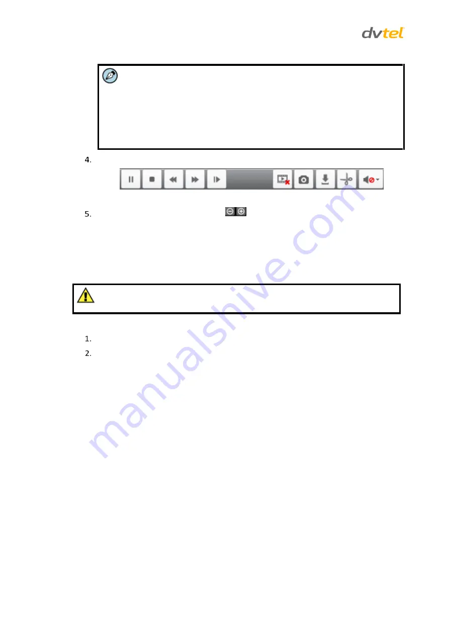
From the toolbar, select the buttons required to perform the desired action.  


Figure 32: Playback Screen Toolbar 


Click the 

Zoom In/Zoom Out

 buttons 

 as neeed. 

5.3


Log 

The operation, alarm, exception and information of the device can be stored in log files, which can 
be viewed and exported at any time. 

The Log function can be used only when the encoder is connected to a network disk.  


Caution:


Make sure the network disk has been initialized for first time use.   

To use the log function 


To enter the 

Log

 screen, click 

Log

.   


In the 

Search Log

 pane, set the log search conditions to refine your search from the 

following options: 


Major Type – All Types, Alarm, Exception, Operation, 

or

 Information 


Minor Type – All Types 


Start Time – 

Select a time and date from the calendar


End Time – 

Select a time and date from the calendar


Summary of Contents for Ariel EN-204

Page 1: ...nted in whole or in part without the express written permission of DVTEL INC DVTEL INC 65 Challenger Road Ridgefield Park NJ 07660 DVTEL INC 65 Challenger Road Ridgefield Park NJ 07660 The contents of...

Page 2: ......

Page 3: ...dio Inputs for Recording on a VMS 10 4 2 7 Connecting Audio Inputs and Output for Two Way Audio Communication 11 4 2 8 Connecting Alarm Inputs from External Devices 12 4 2 9 Connecting Relay Outputs t...

Page 4: ...ork Settings 59 5 4 5 Serial Port Settings 78 5 4 6 Alarm Settings 80 5 4 7 Exception 86 5 4 8 User Management 87 5 4 9 Storage Management 90 5 4 10 Maintenance 91 Appendix 93 A 1 Technical Specificat...

Page 5: ...26 VLC Media Player Screen 26 Figure 27 Playback Screen 28 Figure 28 Playback Screen Toolbar 30 Figure 29 Download File Popup 28 Figure 30 Playback Screen with Callouts 29 Figure 31 Playback Progress...

Page 6: ...ertificate Request Form 76 Figure 74 Bonjour Screen 77 Figure 75 Network Settings Advanced Screen 77 Figure 76 RS 232 Settings Screen 78 Figure 77 RS 485 Settings Screen 79 Figure 78 Alarm Input Armin...

Page 7: ...Alan Singer Third revision Internal release A4 March 20 2014 Alan Singer Revised ActiveX installation A5 March 30 2014 Alan Singer Updated EN 204 photos and schematics with product photos A6 April 10...

Page 8: ......

Page 9: ...rictions and conditions This document contains proprietary information belonging to DVTEL Inc This information is supplied solely for the purpose of assisting explicitly the licensee of the DVTEL unit...

Page 10: ...nt conventions are used throughout this manual A Warning is a precautionary message that indicates a procedure or condition where there are potential hazards of personal injury or death A Caution is a...

Page 11: ...sible shock hazards or damaging the unit assure that the positive and negative of the power leads are properly connected to the terminal block connector before plugging it into the unit or turning on...

Page 12: ...cords should be routed in a manner that prevents safety hazards such as from tripping wire fraying overheating etc Ensure that nothing rests on the unit s cables or power cords Ample Air Circulation...

Page 13: ...the Package The unit package contains the following items QTY Description 1 EN 204 encoder 2 Power adaptors 100 240VDC 50 60Hz EU and US plugs 1 Bag containing five spring clamp terminal block connect...

Page 14: ......

Page 15: ...D indicator that lights in red when the device is powered on and in orange when the SD card is inserted 2 LINE IN 1 x 3 5mm audio input interface to connect to a microphone for two way audio using the...

Page 16: ...troubleshooting 4 RS 485 1 x RS 485 serial interface to connect to PTZ cameras 5 RESET Restores the factory default settings Hold the RESET button for more than 30 seconds while powering the device 6...

Page 17: ...ed so that the air is free to circulate around the unit The unit is protected from direct weather conditions e g sunlight rain dust etc Caution To avoid damage from overheating or unit failure ensure...

Page 18: ...d Warnings page ix Warning 1 To prevent bodily injury or damage to the unit only use properly rated and approved power supplies 2 Make sure that the power supply connection matches the positive and ne...

Page 19: ...e the next section 4 2 4 Configuring the Unit s Initial IP Address Use the DVTEL DNA utility to discover the unit on the network and to set the unit s initial IP address If the encoder is managed by D...

Page 20: ...re 5 EN 204 Login Window Enter the default User Name Admin and Password 1234 Note The user name and password are case sensitive Click Login The EN 204 web interface opens Figure 6 EN 204 Web Interface...

Page 21: ...IP Use DHCP Screen Uncheck Use DHCP Enter the unit s IP address Subnet mask and Gateway IP address in the appropriate field Click Update The unit reboots with the new settings Click on the unit in DNA...

Page 22: ...ce to the encoder Securely connect the coax cable s BNC connector to the analog video output of the camera or video source Connect the BNC connector at the other end of the cable to the VIDEO IN BNC c...

Page 23: ...akers located near the encoder The audio output signal from the unit provides a Line Out 600 impedance level to an amplifier which drives the loudspeakers Figure 11 Two Way Audio Connections Using the...

Page 24: ...device sensor The unit s alarm input relay can be configured in NORMALLY OPEN N O or NORMALLY CLOSED N C mode as shown below Figure 12 Alarm Input Connections For instructions how to set the arming sc...

Page 25: ...e 4 To configure the RS 232 port settings see To configure the RS 232 port page 78 Warning The RS 232 standard specifies a maximum open circuit voltage of 25 volts Exceeding this voltage can cause per...

Page 26: ...1 Restoring Factory Defaults Using the Reset Button A reset button is located on the unit s rear panel See Figure 2 EN 204 Rear Panel page 4 To restore factory defaults using the Reset button Disconn...

Page 27: ...rd The unit s Login screen is displayed See Figure 5 EN 204 Login Window page 8 Enter the user name default Admin and password default 1234 to log into the system The unit s web interface opens See Fi...

Page 28: ...llation Guide 16 Click Next when the Setup ArielWebComponents dialog box opens Figure 15 ArielWebComponents Setup Screen 1 The ArielWebComponents plug in is installed on your PC Figure 16 ArielWebComp...

Page 29: ...ed Figure 17 ArielWebComponents Setup Screen 3 Refresh your screen when the web interface reopens See Figure 6 EN 204 Web Interface page 8 The following pop up message s displayed Figure 18 Run WebVid...

Page 30: ...Spanish Russian Traditional Chinese Simplified Chinese or Japanese User Account Displays the name of the User Account By default Admin is displayed Logout Click Logout to exit the web interface Model...

Page 31: ...s contrast saturation and hue Live View toolbar Buttons for selecting actions in the Live View screen Live View mode button Buttons for selecting the viewing mode 1x1 or 2x2 Live View window Displays...

Page 32: ...the web client to receive and transmit audio through the encoder by attaching an external microphone and loudspeaker This function uses the LINE IN audio jack and the AUDIO OUT jack When the button i...

Page 33: ...d rate PTZ control and address configured in the encoder s RS 485 Settings screen must be the same as the parameters of the connected PTZ camera See RS 485 Port page 13 There are 8 directional buttons...

Page 34: ...stment of pan tilt and zoom Unlike Presets Sequences and Patterns cannot be set from the encoder s web interface They must be set from the camera s interface To create a preset Select a preset number...

Page 35: ...ee Alarm Input page 80 5 1 3 Configuring Video Parameters To configure video parameters Click Video Parameters The Video Parameters pane opens Figure 24 Video Parameters Pane Adjust the slider to cont...

Page 36: ...s click the Start All Recording icon on the toolbar The icon changes to Click the icon to stop recording The pop up message All Record Succeeded is displayed 5 1 4 2 Scheduled Recording To set a recor...

Page 37: ...e URL for the stream in the address bar The syntax for entering in the media player s URL for the main stream is rtsp Admin 1234 xxx xxx xxx xxx mp4 ch1 main av_stream The syntax for entering in the m...

Page 38: ...tallation Guide 26 Note Verify that the values entered in URL string agree with the values set in the Video Settings screen Click Play The video stream is displayed in the media player Figure 27 VLC M...

Page 39: ...2x2 or 3x3 Stop playing Fast forward Stop all channels from playing Download video files Files stored on the microSD card or network disk are formatted in a proprietary format Click this icon to down...

Page 40: ...on the menu bar The Playback screen opens Figure 28 Playback Screen Select a camera from the device list To download a file select one of the following methods Click the Download button to download a...

Page 41: ...re 31 Playback Progress Bar The color of the progress bar represents the different video types Blue A scheduled clip has been selected Red A clip of an alarm has been selected The requested time is in...

Page 42: ...gure 32 Playback Screen Toolbar Click the Zoom In Zoom Out buttons as neeed 5 3 Log The operation alarm exception and information of the device can be stored in log files which can be viewed and expor...

Page 43: ...creen Figure 33 Log Screen Note Up to 100 log files can be displayed in the list Click to save the searched log files to a local directory 5 4 Configuration Device and client PC parameters are set in...

Page 44: ...Settings page 59 Serial Port Settings page 77 Alarm Settings page 80 Exception page 86 User Management page 87 Storage Management page 90 Maintenance page 91 5 4 1 Local Computer Configuration The Lo...

Page 45: ...s Fluency from the drop down list Enter the directory path for saving the following files in the respective text box By default the path is the path created for the web client software on the VMS clie...

Page 46: ...about the encoder Device Name Enter the name you select for the unit in this field Model Displays the encoder model number Serial No Displays the unit s serial number Firmware Version Displays the uni...

Page 47: ...er In the respective text box enter the Server Address NTP Port and Interval number of minutes between requests for synchronization for the NTP server Manual Time Sync to set the time manually In the...

Page 48: ...server refer to Windows Time Service 5 4 3 Camera Settings This section contains instructions how to set basic camera settings To configure camera settings From the Configuration sidebar select Camer...

Page 49: ...y settings From the Channel No drop down list select a camera In the Camera Name text box enter a friendly name for the camera Note This must be a unique name In the OSD Settings area check the option...

Page 50: ...Stream Normal Select the video settings for viewing the main stream Sub Stream Select the video settings for viewing the sub stream Main Stream Event Select the video settings for viewing events Upon...

Page 51: ...y drop down list select Highest Higher Medium Low Lower or Lowest From the Frame Rate drop down list select the number of frames per second FPS from 25 for a PAL system or 30 for an NTSC system to 1 1...

Page 52: ...iguration sidebar select Camera Settings Schedule Settings to configure recording or capture settings The Schedule Settings screen opens on the Record tab Figure 40 Record Schedule Settings Screen 5 4...

Page 53: ...Day To set a recording schedule during different time periods check Customize o Set the Start Time and End Time for each period Note Up to 8 periods can be configured The time of each period cannot be...

Page 54: ...o Overwrite Select Yes or No Record Audio Select Yes or No Expired Time Enter the number of days Enter 0 for continuous recording Click OK when finished To configure the settings on another camera do...

Page 55: ...Accessing the EN 204 via a Web Browser 43 Figure 43 Capture Schedule Settings Screen From the Channel No drop down list select a camera Check Enable Capture Schedule...

Page 56: ...entire day check All Day To set a capture schedule during different time periods check Customize o Set the Start Time and End Time for each period Note Up to 8 periods can be configured The time of e...

Page 57: ...that automatically records video and sends alarms related to motion that has been detected in the surveillance scene This section includes the following topics Configuring Motion Detection Area Settin...

Page 58: ...the Draw Area icon Drag the mouse over a zone in the live video image Use the Sensitivity slider to vary the sensitivity of the motion detection The range is from 1 to 6 The assigned sensitivity is a...

Page 59: ...y default To enter a holiday see Holiday Settings page 56 Set the Start Time and End Time for each period Do one of the following Repeat the above steps for each camera To copy settings of a particula...

Page 60: ...PC in the Video Management System Send Email When an event occurs an email is sent with alarm information to a user or users To configure email settings see Email page 63 Upload to FTP Capture the ima...

Page 61: ...set on the Camera Settings Schedule Settings Advanced screen Note You must select at least one camera in order to record the motion detection event For example when you set motion detection for Camer...

Page 62: ...enter a holiday see Holiday Settings page 56 Set the Start Time and End Time for each period Do one of the following Repeat the above steps for each camera To copy settings of a particular day to the...

Page 63: ...ettings see Email page 63 In the Trigger Alarm Output area do one of the following Check Select All to trigger an external alarm output on both alarm outputs Check A 1 to trigger an external alarm out...

Page 64: ...Click the Trash icon to clear all motion detection areas Repeat steps 3 6 for each zone and for each camera Click Save 5 4 3 8 Tamper proof The Tamper proof function enables you to create an alarm to...

Page 65: ...icon to clear all motion detection areas Use the Sensitivity slider to vary the sensitivity of the drawing Note The sensitivity setting is applied to every zone Repeat steps 2 6 for each zone and for...

Page 66: ...ra Settings Tamper proof Triggered Actions to set the action by which Triggered Actions are taken in the event of camera tampering The Triggered Actions screen opens Figure 54 Tamper Proof Triggered A...

Page 67: ...ect Camera Settings Text Overlay The Text Overlay screen opens Figure 55 Text Overlay Screen From the Channel No drop down list select a camera In the Text Overlay Settings area text box enter text to...

Page 68: ...creen by dragging the text frame 5 4 3 10 Holiday Settings Use the Holiday Settings screen to set certain days with a different recording schedule Up to 32 holidays can be set To activate the Holiday...

Page 69: ...nd End Date from the drop down list Click OK The settings are saved and displayed in the Holiday Settings screen Figure 59 Edited Holiday Settings Note Holiday dates cannot be overlapped 5 4 3 11 Snap...

Page 70: ...formation From the Resolution drop down list select one of the following resolutions For PAL systems 704 576 352 288 default or 176 144 For NTSC systems 704 480 352 240 default or 176 120 Note The EN...

Page 71: ...FTP server enable an event triggered snapshot Do one of the following Repeat the above steps for each camera To copy these settings to all cameras check Select All To copy to a specific camera check...

Page 72: ...the following options 10M Half dup 10M Full dup 100M Half dup 100M Full dup Auto default If your network uses IPv4 DHCP Select this checkbox if your network uses a DHCP server to automatically obtain...

Page 73: ...r Ethernet the MTU is 1500 bytes For PPPoE the MTU is 1492 bytes Preferred DNS Server Enter the primary address of the DNS server used for sending Email Alternate DNS Server Enter the secondary addres...

Page 74: ...ain text box enter the domain name obtained from the www dyndns com website In the User Name text box enter the user name registered in the www dyndns com website In the Password text box enter the pa...

Page 75: ...d Actions page 50 Setting the Tamper Proof Triggered Actions page 54 External Alarm Inputs page 80 Exception page 86 Note Before configuring Email settings check that There is an SMTP mail server on t...

Page 76: ...the number of seconds between two instances of sending picture attachments Attached Image Select this checkbox if you want to send email with attached alarm images Sender Enter the name of the sender...

Page 77: ...ed on your network For SNMPv1 and SNMPv2c a In the Read SNMP Community text box verify that the name is synchronized with the SNMP manager b In the Write SNMP Community text box verify that the name i...

Page 78: ...l d Enter the Authentication Password in the text box e Select the Private key Algorithm DES or AES Note This can be configured only when using the auth priv security level f Enter the Private key pas...

Page 79: ...ettings From the Configuration sidebar menu select Network Settings Port The Port screen opens Figure 65 Port Screen Configure the following settings HTTP Port The default port number is 80 RTSP Port...

Page 80: ...mber used by the FTP server default 21 In the User Name text box enter the user name assigned in the FTP server In the Password text box enter the password assigned in the FTP server In the Confirm te...

Page 81: ...an external hard disk drive HDD and on the built in microSD card You can connect up to 8 disks to the encoder If both the microSD card and HDD are configured as recording media by default the encoder...

Page 82: ...r defined during creating the iSCSI volume of the network storage Select the storage unit type NAS or IP SAN Click Save when finished To view the capacity free space status type and property of each n...

Page 83: ...twork congestion by configuring the priority in which data is sent A QoS aware network can thus allow critical flows to be served before flows with lower priority The encoder can mark the IP header in...

Page 84: ...feature is useful if the encoder is located on a local area network LAN behind a firewall and you need to send Email notifications FTP uploads and alarms to a destination outside the LAN The encoder s...

Page 85: ...col permits devices to automatically discover and establish communication for sharing data with other devices on the network To configure UPnP From the Configuration sidebar menu select Network Settin...

Page 86: ...tes Note In order to enable use of the HTTPS protocol you must first create or request the creation of a secure certificate in the HTTPS screen HTTPS URLs begin with the prefix https After HTTPS is en...

Page 87: ...ation a Country Two letter abbreviation for your country e g US CN etc b Hostname IP Domain name of the server to be protected by SSL e g public yourcompanyname com c Validity Number of days for which...

Page 88: ...rcompanyname com c Password The password to use for accessing the server d State or province Jurisdiction in which your city is located e Locality City f Organization The name of your organization or...

Page 89: ...ration sidebar menu select Network Settings Bonjour The Bonjour screen opens Figure 75 Bonjour Screen Set enable support for Bonjour select the Enable Bonjour checkbox Enter a friendly name for the en...

Page 90: ...erial Port Settings 232 Serial Port The 232 Serial Port screen opens Figure 77 RS 232 Settings Screen Select the settings from the drop down list Default settings are Baud Rate 115200 Select from 300...

Page 91: ...00 Data Bit 8 select from 5 8 Stop Bit 1 select 1 or 2 Parity None select None Even or Odd Flow Control None select None Hardware or Software Verify that the PTZ Protocol is set to Transparent on the...

Page 92: ...is section deals with configuring the following Alarm Input Settings page 83 Alarm Output Settings page 85 5 4 6 1 Alarm Input Settings Four alarm inputs can be connected to the encoder s rear panel S...

Page 93: ...b Figure 79 Alarm Input Arming Schedule Tab From the Alarm lnput No drop down list select an alarm A 1 A 2 A 3 or A 4 From the Alarm Type drop down list select one of the following NC Normally Closed...

Page 94: ...particular day to another day check the day s and click Copy Click OK to save the settings The Edit Schedule Time screen closes and the Alarm Input Arming Schedule tab reopens Note 1 Up to 8 segments...

Page 95: ...vent occurs an ONVIF alarm message is sent to the remote client PC in the Video Management System Send Email When an event occurs an email is sent with alarm information to a user or users To configur...

Page 96: ...and zoom settings Each preset is numbered and enables an operator to quickly jump to that specific position in a live view To enable a Sequence check Enable The Sequence No drop down list is enabled...

Page 97: ...t Configuration Alarm Settings Select the Alarm Input tab The Alarm Input Settings screen opens Figure 81 Alarm Output Settings Tab Select the alarm output 1 or 2 from the drop down list Set the defau...

Page 98: ...or the microSD card Network Disconnected IP Address Conflict Illegal Login Input Output Video Standard Mismatch Video Signal Exception Record Capture Exception Resolution Mismatch Note A video input...

Page 99: ...alarm output on alarm output 2 Click Save 5 4 8 User Management Users are added modified and deleted in the User Management screen Note The Admin user can create normal users Up to 31 users can be cre...

Page 100: ...ser has the following permissions Local log search in local configuration Remote log search in remote configuration Local remote playback in Camera Configuration In the Password text box enter the pas...

Page 101: ...specific camera click the down and select the checkbox Click OK 5 4 8 2 Modifying a User Account To modify a user account From the sidebar menu select Configuration User Management The User Informatio...

Page 102: ...mation Screen Click Delete A popup message is displayed asking if you want to delete this user Click OK The user is deleted 5 4 9 Storage Management The network storage units and the unit s microSD ca...

Page 103: ...orage unit number Click Format to start initializing the unit When the initialization is complete the status of unit becomes Normal From the Property drop down list select one of the following for the...

Page 104: ...re to restore all parameters to the default settings The device reboots after restoring Note Click OK in the dialog box that asks if you want the device to reboot automatically after restoring In the...

Page 105: ...93 Appendix The Appendix includes the following sections Technical Specifications page 94 Network Settings page 96 Connecting Leads to a Spring Clamp Terminal Block page 97 Maximum Video Cable Length...

Page 106: ...Resolution D1 4CIF QCIF 2CIF CIF Main Stream 25 30 FPS PAL NTSC 25 30 FPS PAL NTSC Sub Stream 4 FPS 4 FPS 25 30 FPS PAL NTSC 8 FPS 12 FPS Max Frame Rate Up to 25 30 FPS PAL NTSC D1 Video Bit Rate Main...

Page 107: ...Alarm Input 4 x dry contacts OUT Relay Output 2 x relay outputs Power Source Voltage 12VDC 1A or 802 3af PoE Class 3 Power Consumption 8W Physical Dimensions Dimensions mm 114 48 128 mm W x H x D Dim...

Page 108: ...defined in the units Video streaming multicast Uses the ONVIF address defined by the Video Management System Multicast UDP 9766 Unit self publishing Uses IP address 224 9 9 9 NTP 123 Time synchroniza...

Page 109: ...To connect a wire to the spring clamp terminal block 1 Strip the insulation form the end of each wire that is to be connected to the terminal block Approximately 1 cm 2 54 of wire should be exposed 2...

Page 110: ...mine maximum length for the 75 coaxial cable that connects the camera s analog video output to the encoder Cable Type Maximum Distance Meters Maximum Distance Feet 3 Core RVVP 75 245 7 Core RVVP 375 1...

Page 111: ...0 Fax 44 0 1494 446928 info uk dvtel com INDIA AND SAARC GULF REGION DVTEL India Pvt Ltd 303 SSR Corporate Park Mathura Road Faridabad 121002 Haryana India Tel 91 129 431 5031 Fax 91 129 431 5033 info...

Page 112: ...Call Us or Visit Our Showroom 1300 737 998 3 172 The Entrance Rd Erina...

Reviews: