background image

Controls and Indications 


46


5.3  VIEWING THE INSTRUMENT PAGES 

 
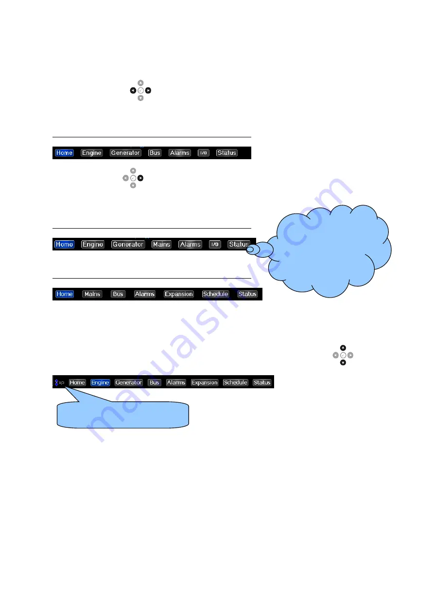
It is possible to scroll to display the different pages of information by repeatedly operating the  

Next & Previous Page 

 buttons

The currently selected page illuminates with Blue 

background. 


Example When Connected To DSE8x10 Controller 


Press the Next Page 

 to view the next instrument page (Engine) etc. Further presses of this 

button returns the display to the Home page. 


Example When Connected To DSE8x20 Controller 


Example When Connected To DSE8x60 Controller 


Once selected the page will remain on the LCD display until the user selects a different page, or after 
an extended period of inactivity, the module reverts to the Home display. 
 

To view additional pages within the current section, press the Instrumentation Scroll 

 buttons.  


If an alarm becomes active while viewing the status page, the display shows the Alarms page to draw 
the operator’s attention to the alarm condition. 
 

If you want to view one 

of the instrument pages 

towards the end of the 

list, it may be quicker to 

scroll left through the 

pages rather than right! 

Indicates that page 1 of 3 within 

The Engine section is displayed. 


Summary of Contents for DSEGenset DSE8004

Page 1: ...DSE8004 Operator Manual ISSUE 2 DEEP SEA ELECTRONICS PLC DSE8004 Operator Manual Document Number 057 229 Author Ashley Senior...

Page 2: ...of this publication should be addressed to Deep Sea Electronics Plc at the address above The DSE logo is a UK registered trademarks of Deep Sea Electronics PLC Any reference to trademarked product nam...

Page 3: ...12 3 7 1 4 ETHERNET PORT 13 3 7 1 4 1 DIRECT MODULE CONNECTION 14 3 7 1 4 2 CONNECTION TO BASIC ETHERNET 15 3 7 1 4 3 CONNECTION TO COMPANY INFRASTRUCTURE ETHERNET 16 3 7 1 4 4 CONNECTION TO THE INTE...

Page 4: ...2 2 INSTURMENT OVERVIEW 50 5 3 2 2 1 WHEN CONNECTED TO DSE8X10 CONTROLLER 50 5 3 2 2 2 WHEN CONNECTED TO DSE8X20 CONTROLLER 50 5 3 2 2 3 WHEN CONNECTED TO DSE8X60 CONTROLLER 50 5 3 3 ENGINE 51 5 3 4...

Page 5: ...8 3 FRONT PANEL EDITOR ACCESS 75 8 3 1 FRONT PANEL EDITOR SECURITY 75 8 3 2 ACCESSING THE DSE8XXX CONTROLLER FRONT PANEL EDITOR OPERATION 76 9 MAINTENANCE SPARES REPAIR AND SERVICING 77 9 1 PURCHASING...

Page 6: ...004 Electronic Engines And DSE Wiring Manual 057 045 Synchronising and Load Sharing Part 1 057 046 Synchronising and Load Sharing Part 2 057 047 Load Share Design and Commissioning 057 082 DSE2130 Op...

Page 7: ...lso has the facility to view the system operating parameters via the LCD display The DSE8x10 module monitors the engine indicating the operational status and fault conditions automatically shutting do...

Page 8: ...Two part connector Male part fitted to module Female part supplied in module packing case Screw terminal rising clamp no internal spring Example showing cable entry and screw terminals of a 10 way co...

Page 9: ...um Input Voltage 24 V DC with respect to plant supply negative Contact Wetting Current 6 mA typical Open Circuit Voltage 12 V typical 3 5 2 CONFIGURED AS OUTPUTS Description Specification Arrangement...

Page 10: ...0 feet RS485 Serial Port Isolated Data connection 2 wire common Half Duplex Data direction control for Transmit by s w protocol Max Baud Rate 115 kbaud subject to configuration External termination re...

Page 11: ...C and the controller to perform a firmware upgrade To connect a module to a PC by USB the following items are required DSE8004 Controller DSE Configuration Suite PC Software Supplied on configuration...

Page 12: ...n of more than one device maximum 20 One advantage of the RS485 interface is the large distance specification which is 1 2 km when using Belden 9841 or equivalent cable This allows for a large distanc...

Page 13: ...tions NOTE DSE stock 2 m 6 5 feet Ethernet Cable DSE Part Number 016 137 Alternatively they can be purchased from any PC or IT store Ethernet is used for point to point cable connection of more than o...

Page 14: ...white orange stripe 2 green solid orange solid 3 white orange stripe white green stripe 4 blue solid blue solid 5 white blue stripe white blue stripe 6 orange solid green solid 7 white brown stripe w...

Page 15: ...Cable Wiring Detail 10baseT 100baseT Pin Connection 1 T568A Connection 2 T568A 1 white green stripe white green stripe 2 green solid green solid 3 white orange stripe white orange stripe 4 blue solid...

Page 16: ...ring Detail 10baseT 100baseT Pin Connection 1 T568A Connection 2 T568A 1 white green stripe white green stripe 2 green solid green solid 3 white orange stripe white orange stripe 4 blue solid blue sol...

Page 17: ...ring Detail 10baseT 100baseT Pin Connection 1 T568A Connection 2 T568A 1 white green stripe white green stripe 2 green solid green solid 3 white orange stripe white orange stripe 4 blue solid blue sol...

Page 18: ...software Modbus Port Number is already in use on the LAN the module cannot be used and another port must be used Outgoing Firewall Rule As the module makes its user interface available to standard web...

Page 19: ...tor be required this can be achieved by using the DSE8004 running editor to configure an auxiliary output for Audible Alarm See section entitled Front Panel Configuration for further details The audib...

Page 20: ...AND MOUNTING 3 9 1 DIMENSIONS 405 mm x 241 mm x 51 mm 15 9 x 9 5 x 2 0 3 9 2 PANEL CUTOUT 359 mm x 204 mm 14 1 x 8 0 3 9 3 DISPLAY DIMENSIONS 210 mm x 160 mm 8 3 x 6 3 265 mm 10 5 Diagonal Across Disp...

Page 21: ...from the clip Insert the three prongs of the fixing clip into the slots in the side of the module case Pull the fixing clip backwards towards the back of the module ensuring all three prongs of the cl...

Page 22: ...es Repair and Servicing elsewhere in this document The supplied silicon gasket provides improved sealing between module and the panel fascia The gasket is fitted to the module before installation into...

Page 23: ...control panel with the optional sealing gasket IP42 front of module when installed into the control panel WITHOUT being sealed to the panel UL508 NEMA rating Approximate 12 Front of module when instal...

Page 24: ...ent enclosure is tilted at an angle up to 15 from it s normal position drops falling at an angle 3 Protected against ingress of solid objects with a diameter of more than 2 5 mm Tools wires etc with a...

Page 25: ...2 IP31 Provides a degree of protection against limited amounts of falling water and dirt 3 IP64 Provides a degree of protection against windblown dust rain and sleet undamaged by the formation of ice...

Page 26: ...le Size Notes 1 DC Plant Supply Input Negative 2 5 mm AWG 13 Connect to a good clean earth point 2 DC Plant Supply Input Positive 2 5 mm AWG 13 Supplies the module and DC Outputs A B C 3 Configurable...

Page 27: ...and multiple DSE modules Belden 9841 Pin No Description Cable Size Notes RS485 SCR RS485 Port Screen 0 5 mm AWG 20 Use only 120 RS485 approved cable Belden 9841 B RS485 Port B 0 5 mm AWG 20 Connect t...

Page 28: ...ds The supply and support of this type of equipment is outside the scope of Deep Sea Electronics PLC Description Cable Size Notes Socket for connection to PC with DSE Configuration Suite Software for...

Page 29: ...efer to section entitled Communication Port Usage elsewhere in this document Description Cable Socket for connection to a single DSE module RS232 Null Modem Cable View looking into the male connector...

Page 30: ...7 128 DSE8005 SCADA Suite Software Manual Description Cable Socket for connection to an existing network to communicate to multiple DSE modules Ethernet Cable View looking into the female connector on...

Page 31: ...Installation 31 4 2 TYPICAL WIRING DIAGRAM 4 2 1 TYPICAL WIRING OF RS485...

Page 32: ...a USB storage device 1 Save the file to the root of a USB storage device with the filename layout xml 2 Insert the USB storage device into the USB host socket 3 Access the DSE8004 Front Panel Configu...

Page 33: ...on the six buttons to the left of the screen are used to provide control of the currently view DSE8xxx controller The navigation buttons are used to navigate through the numerous DSE8004 display pages...

Page 34: ...er as shown below The buttons to the left of the display change according to the selected controller The selected controller is operated using the control buttons to the left of the display or by touc...

Page 35: ...ive and instructs the DSE8x10 module to enter the return delay Should any form of Remote Start Signal be present while operating in this mode a start request to the DSE8x10 module over the MSC Link do...

Page 36: ...n it off load To place the generator on load use the Close Generator button The module automatically instructs the generator to synchronise if required and then closes the generator load switch Close...

Page 37: ...open the breaker Close Generator becomes inactive Further presses of the Open Generator Breaker button have no effect Close Generator The Close Generator button control the operation of the generator...

Page 38: ...s to the Start button to start the generator and run it off load To place the generator on load use the Close Generator button The module automatically instructs the generator to synchronise if requir...

Page 39: ...ator is available it is automatically placed on load Close Generator becomes active synchronising to the Mains if required Depending upon module configuration the generator remains in constant paralle...

Page 40: ...ator Bus to the Mains Once done the Generator Bus load switch opens Close Bus becomes inactive leaving just the mains supplying the load Alternative Breaker Button Control Synchronising NOT Enabled Pr...

Page 41: ...Mains to the Generator Once done the Mains load switch opens Close Mains becomes inactive leaving just the Generator supplying the load Alternative Breaker Button Control Synchronising NOT Enabled Pre...

Page 42: ...The module then waits for next start event Manual Mode This button places the module into its Manual Mode Once in Manual Mode the module responds to the Start button to send a start request to the DSE...

Page 43: ...edback from the DSE8x10 module to confirm the generator bus is available Once the generator bus is available it is automatically placed on load Close Bus becomes active synchronising to the Mains if r...

Page 44: ...ator Bus to the Mains Once done the Generator Bus load switch opens Close Bus becomes inactive leaving just the mains supplying the load Alternative Breaker Button Control Synchronising NOT Enabled Pr...

Page 45: ...ains to the Generator Bus Once done the Mains load switch opens Close Mains becomes inactive leaving just the Generator Bus supplying the load Alternative Breaker Button Control Synchronising NOT Enab...

Page 46: ...Example When Connected To DSE8x60 Controller Once selected the page will remain on the LCD display until the user selects a different page or after an extended period of inactivity the module reverts...

Page 47: ...l Configuration for more details Touch the screen in the area of the Configurable Widgets to cycle through the different configured display options The available displays are as shown in the examples...

Page 48: ...r is shown when no other page has been selected It is also the page that is automatically displayed after a period of inactivity of the module control buttons The parameters that are displayed changes...

Page 49: ...PE DISPLAY During synchronisation the kW and kVAr percentage bars are replaced by the synchroscope as shown below Voltage difference between the two supplies Frequency difference between the two suppl...

Page 50: ...mples below This serves as an overview of the measured instruments of the viewed DSE Controller Further information is viewed using the Instrument Pages as detailed below 5 3 2 2 1 WHEN CONNECTED TO D...

Page 51: ...ion gathered about the engine which may be obtained using a CAN link The content may change depending upon the selected engine and the features supported by the engine To view additional pages within...

Page 52: ...elow Parameter Inactive Grey Warning Yellow Shutdown Red Water In Fuel After Treatment Inlet Temperature Charge Alternator Oil Pressure Fuel Level Battery Voltage Coolant Temperature ECU Lamp Paramete...

Page 53: ...viewed DSE controller Press the Instrumentation Scroll buttons to cycle between the parameters The instrumentation values are displayed in the form of either analogue meters or bar graphs depending on...

Page 54: ...ewed DSE controller Press the Instrumentation Scroll buttons to cycle between the parameters The instrumentation values are displayed in the form of either analogue meters or bar graphs depending on D...

Page 55: ...wed DSE controller Press the Instrumentation Scroll buttons to cycle between the parameters The instrumentation values are displayed in the form of either analogue meters or bar graphs depending on DS...

Page 56: ...f events displayed depends on the space available with the chosen font The event log page will display the event index event type date time and number of hours run for each event Electronic engine dia...

Page 57: ...arting with the DSE8xxx s Inputs followed by outputs and expansion modules 5 3 8 1 DIGITAL INPUTS The digital inputs screen displays the status of each digital inputs on the DSE8xxx module The screen...

Page 58: ...gue input is configured as a digital input a dial displayed with a low high message instead of the value Press the Instrumentation Scroll to select the required DSE2130 module 5 3 8 4 DSE2131 EXPANSIO...

Page 59: ...current values of the analogue inputs Press the Instrumentation Scroll to select the required DSE2133 module 5 3 8 6 DSE2152 EXPANSION MODULE The DSE2152 screen displays the status of all attached DS...

Page 60: ...nd open closed status of the digital outputs Press the Instrumentation Scroll to select the required DSE2157 module 5 3 8 8 DSE2548 EXPANSION MODULE The DSE2548 screen displays the status of all attac...

Page 61: ...half of the screen A title string shown here as Scheduler Disabled shows the scheduler enabled mode and load configuration status and a table shows each scheduler entry details The lower half of the s...

Page 62: ...munication ports in use by the DSE8004 5 3 10 2 COMMISSIONING SCREENS An optional commissioning screen is available via an option in the running editor When enabled press the Instrumentation Scroll to...

Page 63: ...g description details the sequences followed by a module containing the standard factory configuration Remember that if you have purchased a completed generator set or control panel from your supplier...

Page 64: ...module s operation 6 1 1 SELECTING THE ENGINE 6 1 2 STARTING THE ENGINE Select the desired engine as shown above First select manual mode then press the Start button to crank the engine Touch the scre...

Page 65: ...age buttons and locate Fuel Level The Manual Fuel Pump Icon is shown on the display to indicate that this feature is available when Manual Fuel Pump Control is enabled in the module s configuration Th...

Page 66: ...ntroller and press and hold the Tick button to enter the Running Editor Navigate to the Generator Generator Frequency section Press the Tick button to enter edit mode Press Instrumentation Scroll to c...

Page 67: ...pressing the Alarm Mute Lamp Test button The Alarm popup box is colour coded to indicate the level of the alarm To clear the alarm popup box press the Tick button Alarm Level Colour Title Graphic Warn...

Page 68: ...uration to the controller that has Protections Disabled configured results in a warning message appearing on the PC screen for the user to acknowledge before the controller s configuration is changed...

Page 69: ...al trips are latching and stop the Generator but in a controlled manner On initiation of the electrical trip condition the module will de energise the Close Generator Bus Output to remove the load fro...

Page 70: ...uration mode allows the operator limited customising of the way the module operates Use the module s navigation buttons to traverse the menu and make value changes to the parameters Previous Section I...

Page 71: ...or items available for editing and the right hand side shows the current value Press the Instrumentation Scroll buttons to select the section you wish to view change Press the Next Previous Page butto...

Page 72: ...able Disable Active Left Alarms Enable Disable Comms Enable Disable Engine Enable Disable Digital Inputs Enable Disable Digital Outputs Enable Disable Instrumentation Enable Disable Chart Enable Disab...

Page 73: ...lectrical Trip Common Alarm Combined Maintenance Alarm Audible Alarm Not Used Output B Output Source Communications Link Lost Emergency Stop Common Warning Common Shutdown Common Electrical Trip Commo...

Page 74: ...Front Panel Configuration 74 Section Parameter Selection Time Module Time HH MM SS Module Date MM DD YYYY or DD MM YYYY Firmware Upgrade Version Layout Update Files Available Files...

Page 75: ...er selected or one of the DSE8xxx controller s instrument pages A simultaneous press of the Stop Reset Mode button and Tick button enters the front panel editor A press and hold of the Tick button exi...

Page 76: ...th a box In order to start editing an item press the Tick button at which point the item and current value are highlighted In addition the image shown below appears to the right of the current value t...

Page 77: ...additional plugs from DSE please contact our Sales department using the part numbers below 9 1 1 INDIVIDUAL PLUGS Module Terminal Designation Plug Description Part No 1 8 8 way 5 08mm 007 164 RS485 R...

Page 78: ...sale For full details of any applicable warranty refer to the original equipment supplier OEM 11 DISPOSAL 11 1 WEEE WASTE ELECTRICAL AND ELECTRONIC EQUIPMENT If you use electrical and electronic equi...

Page 79: ...This Page is left blank intentionally...

Page 80: ...This Page is left blank intentionally...

Reviews: