


Eco-65 Installation and Operation Manual
98
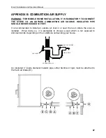
To complete the installation, make a hole of1/4" to 1/2" (6 mm à 13 mm) bigger than the
insulate pipe diameter in the outside wall of the house at the chosen location. From
outside, place the outside air inlet cap (E) in the hole (open side down) and fasten the
register to the wall, with screw. Place the insulated pipe (A) over the register tube and over
the fireplace outside air connector (D). At each end, carefully pull back the insulation and
plastic cover, exposing the flexible pipe. Attach the flexible pipe using pipe clamps(C). For
a better seal, you may also use aluminum tape. Wrap the tape around the joint between
the flexible pipe and the air inlets. Carefully push the insulation and plastic cover back over
the pipe. Fix the plastic in place using aluminum tape.
A rodent guard (minimum 1/4” wire mesh) must be used at the termination. All connections
must be secured and airtight by either using the appropriately sized hose clamp and/or UL-
181-AP foil tape.
Make sure that the fresh air intake back draft shutter
(A)
functions freely. The fresh air
intake back draft shutter is located in the back of the stove.
Summary of Contents for ECO-65
Page 67: ...Eco 65 Installation and Operation Manual 67 9 Wiring Diagram ...
Page 79: ...Eco 65 Installation and Operation Manual 79 14 Exploded View and Replacement Parts SECTION A ...
Page 80: ...Eco 65 Installation and Operation Manual 80 SECTION B ...
Page 81: ...Eco 65 Installation and Operation Manual 81 SECTION C ...
Page 82: ...Eco 65 Installation and Operation Manual 82 SECTION D SECTION E ...
Page 83: ...Eco 65 Installation and Operation Manual 83 SECTION F SECTION G ...
Page 84: ...Eco 65 Installation and Operation Manual 84 SECTION H SECTION I ...
Page 85: ...Eco 65 Installation and Operation Manual 85 SECTION J ...


