


Eco-65 Installation and Operation Manual
58
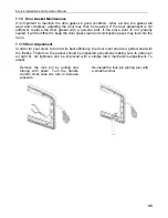
that could have caused a jam. Clean the
auger housing thoroughly to remove all pellet
dust.
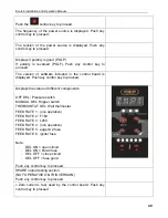
5. The flue temperature sensor failed.
The “thermistor” is a heat sensor located on
the exhaust motor housing. Its function is to
tell the control board that the stove has
ignited properly by measuring the heat at the
exhaust. The pellet stove will not start feeding
pellets at the desired heat setting until it has
received a signal from the thermistor heat
sensor. If the thermistor heat sensor is faulty,
the unit will stop after the ignition cycle. To
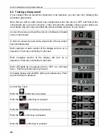
display the temperature reading from the
thermistor press and hold the + and auger
buttons for 3 seconds. Confirm that the value
displayed is equal to the ambient temperature
in the room where the appliance is installed.
If this is the case, turn on the stove and
check the same temperature display. If after
10 minutes, the value has not increased
despite the unit is in operation this means
that the temperature sensor is disconnected
or defective. If the temperature rises, the
problem may be with the feed rate or pilot
mode. Depending on many factors (ambient
temperature, pellet quality, etc) the heat
produced by the stove may not be sufficient
to keep the exhaust temperature high
enough. To resolve the situation increase
feed rate (see
Section 5.2.1: Selecting the
Combustion Level (Heat Rate)
)
.
NOTE: IF THE HOPPER AUGER MOTOR FAILED OR THE HOPPER AUGER IS JAMMED,
TO AVOID PELLET SPILLAGE, EMPTY THE HOPPER OF ITS CONTENTS BEFORE
EXECUTING THE FOLLOWING TESTS.
Summary of Contents for ECO-65
Page 67: ...Eco 65 Installation and Operation Manual 67 9 Wiring Diagram ...
Page 79: ...Eco 65 Installation and Operation Manual 79 14 Exploded View and Replacement Parts SECTION A ...
Page 80: ...Eco 65 Installation and Operation Manual 80 SECTION B ...
Page 81: ...Eco 65 Installation and Operation Manual 81 SECTION C ...
Page 82: ...Eco 65 Installation and Operation Manual 82 SECTION D SECTION E ...
Page 83: ...Eco 65 Installation and Operation Manual 83 SECTION F SECTION G ...
Page 84: ...Eco 65 Installation and Operation Manual 84 SECTION H SECTION I ...
Page 85: ...Eco 65 Installation and Operation Manual 85 SECTION J ...


