


Eco-65 Installation and Operation Manual
32
6.2 Everyday Startup
Before starting the stove, make sure there is enough pellets in the hopper and that the
recommended maintenance schedule has been followed (see
Section 7.1.1:
Recommended maintenance schedule
). Press the
icon for either MANUEL or
THERMOSTAT.
6.3 Running Out of Pellets
If your stove runs out of pellets, the fire will slowly go out; the convection fan will run until the
heat sensor on the exhaust fan reads 115°F. The cooling cycle will take a few minutes before
all other motors stops. When this temperature is reached, a warning message
will appear
on the screen.
To restart the stove, wait until all components stop running (usually 10 minutes after the
warning message has been displayed). Press the
button, refill the hopper, and press
the auger icon
.
6.4 Refueling
While the stove is running, you have up to 3 minutes to refill the hopper with pellets. Note that
opening the hopper lid will stop the auger from feeding pellets to the stove. If the hopper lid is
left open more than 3 minutes, the stove will stop and a warning code
will appear on the
control panel. To restart the stove, close the lid, press the
button, and then press the
to select either MANUAL or THERMOSTAT.
NOTE: Keep hopper lid closed at all times except when refueling. Do not overfill the
hopper.
6.5 Shutting Down Procedure
To turn your stove off, press the
button on the control panel until the LED light is in the
OFF position. The cooling cycle will take a few minutes and the blowers will continue to
function while the stove is cooling down.
IMPORTANT: DO NOT DISCONNECT THE POWER CORD TO TURN OFF THE STOVE.
6.6 Operating the Stove Using a Thermostat
A thermostat may help you maintain a constant house temperature automatically (
See
APPENDIX D: Thermostat installation (AC05558)
). A Low voltage thermostat is required. A
fixed wall mount or hand held model can be used.
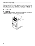
Summary of Contents for ECO-65
Page 67: ...Eco 65 Installation and Operation Manual 67 9 Wiring Diagram ...
Page 79: ...Eco 65 Installation and Operation Manual 79 14 Exploded View and Replacement Parts SECTION A ...
Page 80: ...Eco 65 Installation and Operation Manual 80 SECTION B ...
Page 81: ...Eco 65 Installation and Operation Manual 81 SECTION C ...
Page 82: ...Eco 65 Installation and Operation Manual 82 SECTION D SECTION E ...
Page 83: ...Eco 65 Installation and Operation Manual 83 SECTION F SECTION G ...
Page 84: ...Eco 65 Installation and Operation Manual 84 SECTION H SECTION I ...
Page 85: ...Eco 65 Installation and Operation Manual 85 SECTION J ...


