background image

16

9.   ASSEMBLY

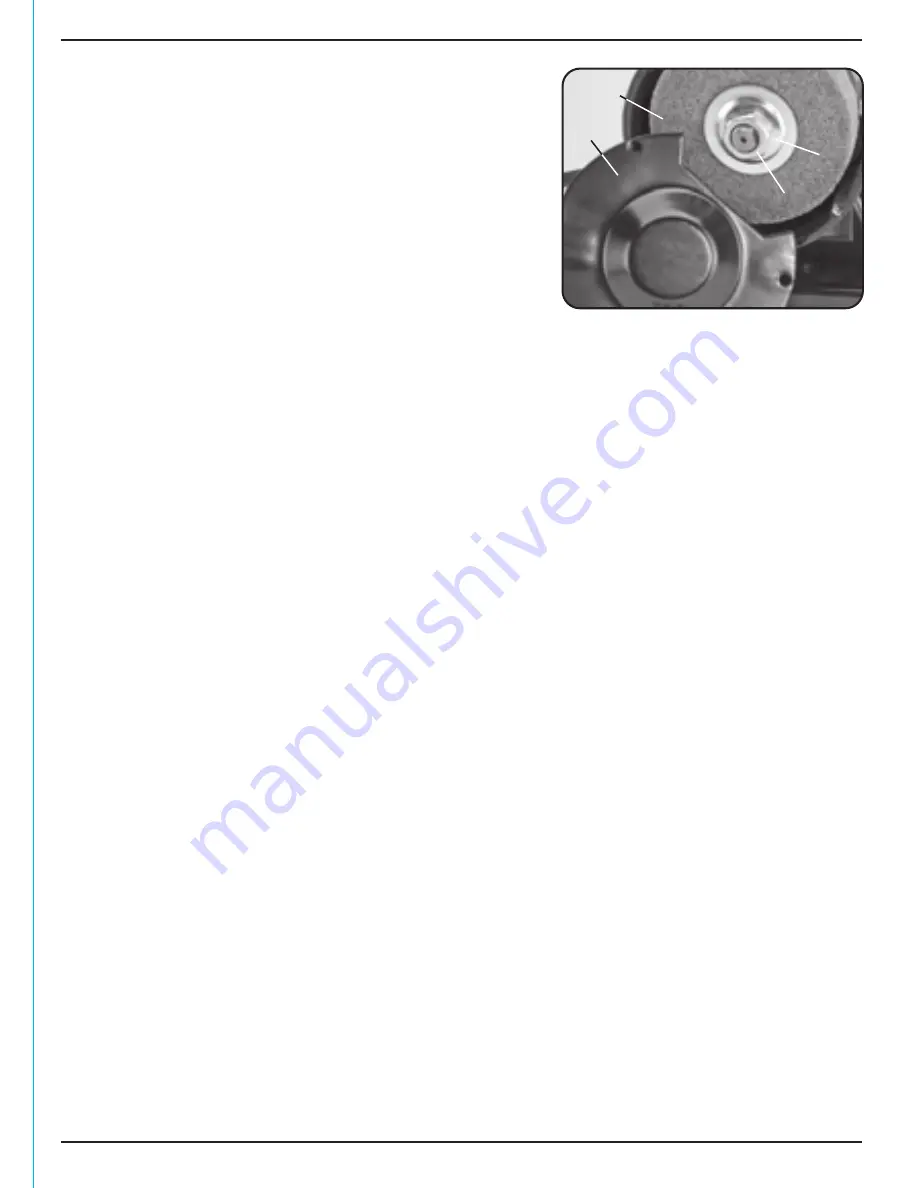
FIG.3

9.4 FITTING/REPLACING THE GRINDING & 

POLISHING WHEELS – FIG.3:

Note:

 Remove the plug from the socket before 

carrying out adjustment, servicing or maintenance.

Warning

! Do not use damaged grinding wheels.

–  Switch the grinder off and disconnect the power 

supply. Remove the screws, spring clips and washers 
holding the wheel guard 

, and remove the cover 

.

–  Holding the other wheel by hand, remove the 

locking nut 

and flange 

. Slide off the old 

grinding wheel.

Use only grinding wheels recommended by the manufacturer which has a marked speed 
equal or greater than the speed marked on the nameplate of the tool and have a maximum 
dimension no greater than: 

–  75mm diameter, 20mm thickness with a corresponding bore size of 10mm.

Abrasive products shall be subjected to a visual inspection as received before mounting.

In addition, a ring test shall be executed for vitrified wheels with D>80mm.

Damaged abrasive products should be destroyed.

Note:

 The left hand grinding wheel locking nut has a left handed thread. When fitting a new 

grinding wheel, always check that the stated max. RPM on the wheel exceeds the RPM of the 
bench grinder. Also, inspect the new wheel for any damage, such as flaws or cracks. If the 
wheel appears satisfactory, fit it to the grinder.

–  Replace the flange and locking nut securely. Do not overtighten to avoid damage to the 

wheel. Re-assemble the guard fully prior to carrying out testing.

–  Each time after mounting, the wheel should be test run for a reasonable time.

Warning! 

The specified maximum operating speed of the wheel must not be exceeded.

A bench grinder is designed for hand grinding operations only, such as sharpening drill bits, 
chisels and screwdrivers or removing excess metal from work pieces.

A coarse grit abrasive wheel could be used for rough metals, to remove large amounts of 
metal or where a smooth finish is not important.

A fine grit abrasive wheel could be used for sharpening tools or grinding close to size. A fine 
grit wheel removes metal more slowly and therefore gives the work piece a smooth finish 
and does not generate enough heat to anneal the cutting edges.

Note:

 Remove the plug from the socket before carrying out adjustment, servicing or 

maintenance.

–  Check that the eyeshields have been secured in the correct position and that the grinding 

wheel lock nuts are tight.

–  When grinding, always keep the work piece moving across the face of the wheel. 

Grinding against the same part of the wheel will cause uneven wear of the wheel face.

–  When necessary, dress the abrasive wheels using a wheel dressing tool. After dressing, 

adjust the tool rests and spark deflectors as necessary to maintain a 1.5mm clearance 
from the wheel.

Summary of Contents for 27628

Page 1: ...s been designed and contains all the necessary information to ensure its correct and safe use By following all the general safety instructions contained in this manual it will ensure both product and...

Page 2: ...UNDERSTANDING THIS MANUALS SAFETY CONTENT WARNING Information that draws attention to the risk of injury or death CAUTION Information that draws attention to the risk of damage to the product or surr...

Page 3: ...KNOW YOUR ACCESSORIES 12 9 ASSEMBLY 9 1 SPARK DEFLECTORS EYESHIELDS 15 9 2 TOOL RESTS 15 9 3 BENCH MOUNTING YOUR GRINDER 15 9 4 FITTING REPLACING THE GRINDING POLISHING WHEELS 16 9 5 FITTING THE FLEXI...

Page 4: ...chase except where tools are hired out when the guarantee period is 90 days from the date of purchase This guarantee does not apply to normal wear and tear nor does it cover any damage caused by misus...

Page 5: ...hing 75 20mm 10mm bore fibrous Wheel dimensions Max diameter 75mm Max thickness 20mm Bore diameter 10mm Flexible shaft Length 1 1M Collet sizes 2 0 2 4 3 2mm Shaft bit 1 8 Sound power level 85dB A Sou...

Page 6: ...way locked up and from children Do not overload or misuse the tool All tools are designed for a purpose and are limited to what they are capable of doing Do not attempt to use a power tool or adapt it...

Page 7: ...of handling the current amps drawn by the machine in use Fully extend the lead regardless of the distance between the power supply and the tool Excess current amps and a coiled extension lead will bo...

Page 8: ...such a manner that they are not subjected to mechanical damaged and harmful environmental influences c Selection of the abrasive product Information on the label or the abrasive product as well as re...

Page 9: ...be ensured that the abrasive product has stopped 5 4 CONNECTION TO THE POWER SUPPLY Caution Risk of electric shock Do not open Make sure the power supply information on the machine s rating plate are...

Page 10: ...10 6 TECHNICAL DESCRIPTION Power On Off switch On Off variable speed dial Adjustable tool rest Spark deflector Eyeshield Abrasive wheel Polishing wheel Wheel guard Flexible shaft 6 1 IDENTIFICATION...

Page 11: ...tained at least during the guarantee period in case the machine needs to be returned for repair Warning Some of the packaging materials used may be harmful to children Do not leave any of these materi...

Page 12: ...al grinding stone pink 120 grit 1 Long cylindrical grinding stone green 120 grit 1 HSS Cutting Burrs Key Description Qty Grinding Stones Key Description Qty HSS cutting burr ball 1 HSS cutting burr po...

Page 13: ...ndrical grinding stone white 80 grit 1 Spherical grinding stone white 80 grit 1 8 ACCESSORY KIT Large sanding drum 120grit 4 Small sanding drum 120grit 4 Large sanding drum mandrel 1 Small sanding dru...

Page 14: ...ng compound 1 Sharpening stone 1 Sanding and Cutting Discs Key Description Qty Miscellaneous Key Description Qty Large sanding discs 120grit 36 Small sanding discs 120grit 25 Fibreglass cutting discs...

Page 15: ...nch grinder with the eyeshields cracked missing or incorrectly positioned The eyeshield must remain between the user and abrasive wheel 9 2 TOOL RESTS FIG 2 Fit both tool rests to the brackets located...

Page 16: ...it it to the grinder Replace the flange and locking nut securely Do not overtighten to avoid damage to the wheel Re assemble the guard fully prior to carrying out testing Each time after mounting the...

Page 17: ...the flexible drive shaft When the key is correctly slotted in place the driveshaft is locked enabling the chuck cover to be removed Use the spanner provided to unscrew the chuck cover Insert a correct...

Page 18: ...it centrally onto the mandrel The thread of the mandrel will securely bind into the fibrous body of the disc FIG 10 9 7 FITTING A SANDING DRUM ACCESSORY FIG 8 Following the steps outlined above in sec...

Page 19: ...t to correct angle Present the workpiece smoothly on to the grinding wheel face with a light and even pressure without causing the wheel to slow Best results are achieved if the grinder is allowed to...

Page 20: ...olish across marks or scratches and not along them Before polishing remove any lacquered surfaces from the workpiece with paint remover Don t mix different polishing compounds on the same wheel A slig...

Page 21: ...e carrying out any maintenance or troubleshooting 11 2 MAINTENANCE Regular inspection and cleaning reduces the necessity for maintenance operations and will keep your tool in good working condition Th...

Page 22: ...22 12 OPTIONAL ACCESSORIES 30479 AG100 150mm Grinding wheel dresser Stock No Part No Description 12 1 OPTIONAL ACCESSORIES The following accessories are available from your local Draper stockist...

Page 23: ...power tools with domestic waste Do not incinerate Do not abandon in the environment Do not dispose of WEEE as unsorted municipal waste Waste Electrical Electronic Equipment 14 EXPLANATION OF SYMBOLS...

Page 24: ...U K Helpline 023 8049 4344 Sales Desk 023 8049 4333 General Enquiries 023 8026 6355 Service Warranty Repair Agent For aftersales servicing or warranty repairs please contact the Draper Tools Helpline...

Reviews: