CONTACT US AT
www.DRpower.com
or CALL TOLL FREE
1-800-DR-OWNER
37
9.
Install a new or sharpened Knife as shown with the Knife edge facing up and towards you and finger
tighten the Allen screws and Lock Nuts (use the new hardware supplied with a new Knife kit) to hold
n
Belt Guard.
if needed adjust the gap between the Knife and Wear Plate (See “Checking a
g
the K
te Gap” in this Chapter).
Removing and
the Knife to the Flywheel.
10.
Using a 7/32” Allen wrench and a 1/2” socket, tighten the center Screw and Locknut, then tighte
the outer Screw and Locknut, and finally tighten the inner Screw and Locknut.
11.
Double-check that all three Locknuts on the Allen Screws are tight.
12.
Reinstall the two Access Covers.
13.
Replace the
14.
Check and
nd Adjustin
nife to Wear Pla
Replacing the Wear Plate
Remove the Hopper (See “Inspecting the Chipper
Knife and Wear Plat
1.
e” in this Chapter)
e Wear Plate to the Chipper Assembly and
3.
.
Checki
2.
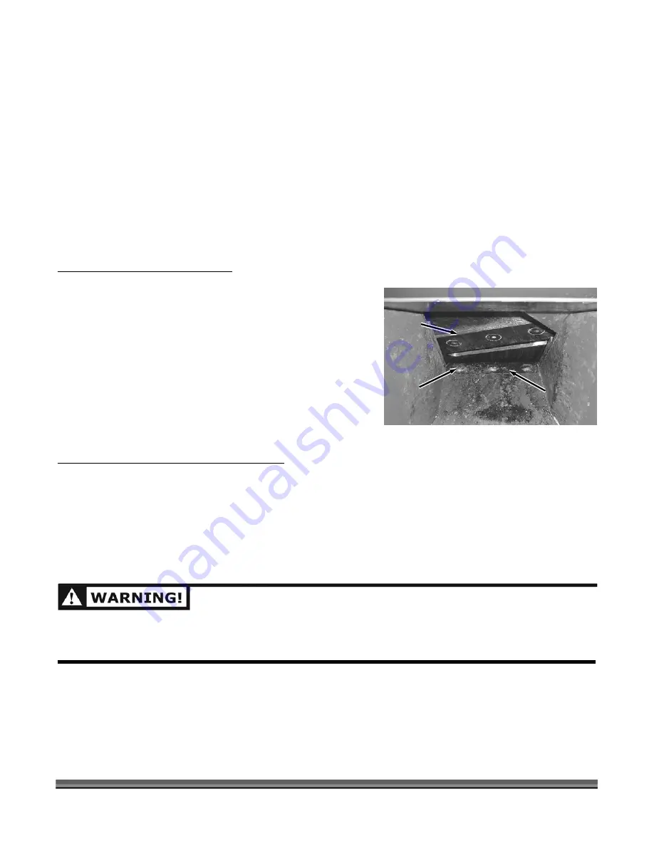
Remove the three Locknuts and Carriage Bolts that
attach th
then remove the Wear Plate (
Figure 36
).
Install the new Wear Plate and secure with the
Carriage Bolts and Locknuts.
Carriage B
NOTE: The Gap between the Knife and Wear Plate must be
adjusted whenever the Wear Plate is removed. See the
following instructions
ng and Adjusting the Knife to Wear Plate Gap
When you replace the Knife you must check and set the clearance between the Knife and Wear Plate. Set
this clearance or gap to 1/16" by using the Gap Tool that is supplied with the Chipper and a new Knife
kit. If the gap between the Wear Plate and the Knife is not set correctly, you will have excessive vibration
ip
ll seem to be dull. The Wear Plate should have a square edge and be free
of dents or gouges. The Wear Plate can be hand sharpened (see steps below). Be careful not to
ge the characteristics of the steel and you will
then
Tools Needed:
ch ping and the Knife wi
when
overheat it during the sharpening process. This will chan
have to replace the Wear Plate.
olt
and Locknut
Figure 36
Wear
Plate
Chipper
Knife
SHUT
REMO
TTERY CABLE, THEN WAIT 5 MINUTES
BEFORE PER
DOWN THE ENGINE, WAIT FOR ALL MOVING PARTS TO
VE SPARK PLUG WIRES, DISCONNECT THE NEGATIVE BA
FORMING ANY MAINTENANCE PROCEDURE OR INSPECTION ON THE CHIPPER.
COME TO A COMPLETE STOP,
•
7/16" wrench or socket
•
Gap Gauge (provided with Chipper)
Summary of Contents for 30.00 COMMERCIAL RAPID-FEED CHIPPER
Page 9: ...241821 241841 CONTACT US AT www DRpower com or CALL TOLL FREE 1 800 DR OWNER 5...
Page 16: ...12 30 00 COMMERCIAL DR RAPID FEED CHIPPER...
Page 24: ...20 30 00 COMMERCIAL DR RAPID FEED CHIPPER...
Page 32: ...28 30 00 COMMERCIAL DR RAPID FEED CHIPPER...
Page 50: ...46 30 00 COMMERCIAL DR RAPID FEED CHIPPER...
Page 65: ...CONTACT US AT www DRpower com or CALL TOLL FREE 1 800 DR OWNER 61...
Page 71: ...CONTACT US AT www DRpower COM or CALL TOLL FREE 1 800 DR OWNER 67 Schematic Chipper Basic...
Page 73: ...CONTACT US AT www DRpower com or CALL TOLL FREE 1 800 DR OWNER 69 Schematic Hopper Assembly...
Page 75: ...CONTACT US AT www DRpower com or CALL TOLL FREE 1 800 DR OWNER 71 Schematic Accessories...
Page 76: ...72 30 00 COMMERCIAL DR RAPID FEED CHIPPER...
Page 77: ...Notes CONTACT US AT www DRpower com or CALL TOLL FREE 1 800 DR OWNER 73...
Page 78: ...74 30 00 COMMERCIAL DR RAPID FEED CHIPPER Notes...


