9
Power Connection
4.3
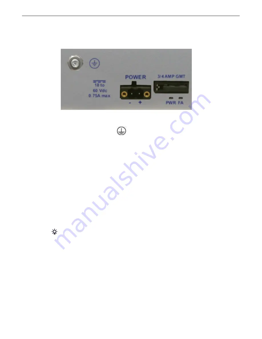
The NetGuardian 224A uses single or dual (Optional) power inputs, powered through two barrier plug power
connectors.
NetGuardian 224A Power Terminals and Fuses
To connect the NetGuardian 224A to a power supply:
1. Locate the metal grounding lug next to the symbol
. Use the grounding lug to connect the unit to earth
ground.
2. Insert the eyelet of the earth ground cable between the two nuts on the grounding lug (Ground cable not included).
3. Choose a barrier plug power connector to attach your power cable to. One plug is used for main power and the
other is used for backup power. Both plugs are interchangeable so it does not matter which plug you select. Each
plug's right terminal is Ground and its left terminal is Battery Lead.
4. Insert a battery return into the power connector plug's right terminal (+) and tighten the screw.
5. Insert a battery lead to the plug's left terminal (-) and tighten its screw.
6. Insert fuse into the fuse distribution panel.
7. Check the power status LED for polarity. The LED will be off if polarity is wrong, and green if it is correct.
8. Measure voltage. Connect the black cable onto the ground connector of your Digital Voltage Meter (DVM) and red
cable onto the other connector of your DVM. The voltmeter should read between the values listed on the silk
screen next to the power connector.
9. Insert the local fuse into the power fuse slot. The power plug can be inserted into the power connector only one
way to ensure the correct polarity.
Note
: The negative voltage terminal is on the left and the (+) terminal is on the right.
10.Verify that the
LED is lit. To confirm that power is correctly connected, the front panel status LED will flash
GREEN and RED, indicating that the firmware is booting up.
Summary of Contents for D-PK-NG224-12003
Page 9: ...5...
Page 11: ...7 Optional Shipping Items Available by Request 3 1 Small WAGO connector 2 802 01020 00...
Page 16: ...12 66Block diagrams 6 3 66 block pinout for Amphenol 1 TTL Discretes 1 24...
Page 17: ...13 66 block pinout for Amphenol 2 Controls 1 2...
Page 77: ...73...
Page 78: ......


