


28
Saflok RT/RT Plus Installation Guide PK3720_T 04-19
B.3
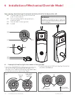
Install the Cylindrical Unit
The lock is factory shipped with spacers for doors of 1 3/4"
thickness. For doors of other thicknesses remove the two
screws (06 of fig. 2) and as per table 1 install the required
componants (06), (07) and (08) as indicated.
CAUTION
WARNING
IMPORTANT
It is very important to assemble the spacers in position
shown.
HANDING
1. Lock with 2 DIFFERENT SPACERS (see fig. 2) The cylindrical Unit and Attachement Plate assembly is shipped assembled
in the factory for 1 3/4" door thickness (44mm) with 2 "07" spacers, 1 "08" spacer and 2 "06" 5/8" LG (see fig.4) flat head
screws.
Fig. 3
Screw Length (Full Scale)
Length 3/8"
Length 1/2"
Length 5/8"
Length 3/4"
Length 7/8"
Door Thickness
Spacer
Spacer
Screw
07
08
06
1-3/8" (35mm) to 1-9/16" (40mm)
2
-
3/8 (10mm)
1-5/8" (41mm) to 1-11/16" (43mm)
1
1
1/2 (13mm)
1-3/4" (44mm) to 1-13/16" (46mm)
2
1
5/8 (16mm)
1-7/8" (48mm) to 1-15/16" (49mm)
-
2
5/8 (16mm)
2" (51mm) to 2-1/16" (52.5mm)
1
2
3/4 (19mm)
2-1/8" (54mm) to 2-3/16" (56mm)
2
2
3/4 (19mm)
2-1/4" (57mm) to 2-5/16" (59mm)
-
3
7/8 (22mm)
2-3/8" (60mm) to 2-1/2" (64mm)
1
3
7/8 (22mm)
Door Thickness Table 1
See 2
Screws
Attachement Plate
Cylindrical Unit Assembly
Fig. 2
Fig. 1
07
08
06
APPENDIX B Installing Cylindrical Models 23/8" &
23/4" Backset


