


Saflok RT/RT Plus Installation Guide
PK3720_T 04-19 27
APPENDIX B Installing Cylindrical Models 23/8" &
23/4" Backset
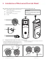
B.1
Install the Strike
Follow the same steps as for a mortise model strike (see
page 8, all steps in section 3.2). Note that the handle height
is aligned with the center of the strike.
CAUTION
WARNING
IMPORTANT
For cylindrical latch models, ensure the dead-locking pin will
stop against the strike when the door is closed (see figure).
An incorrect installation that permits the pin to slip inside the
strike may result in a total lockout and will void the warranty
of the complete lock mechanism.
Correct
Incorrect
4
6
B.2
Install the Latch
Follow the instructions on page 9, all steps in section 3.3.
Note that for cylindrical models, the axis of rotation of the
handle is level with the center of the strike. Mark this height
on the edge of the door in step 1 on page 8.
CAUTION
WARNING
IMPORTANT
Respect applicable building codes regarding handle height.
1. Drill the hole for the latch, and chisel out clearance for the
latch plate according to the template.
2. Drill the holes for the cylindrical unit, thumbturn spindle,
and lock mounting screws. Refer to template for dimen-
sions and depths.
CAUTION
WARNING
IMPORTANT
Drill from both sides of the door to prevent unsightly dam-
age.
3. Install the latch (O) using 1" Phillips mounting screws. Posi-
tion the deadlocking pin (Q) opposite to the closing direc-
tion as shown.
4. Install strike and strike dust box.
CAUTION
WARNING
IMPORTANT
Use only the strike and strike box supplied. The use of non-
approved parts will result in a functionality problem and
may void the warranty.
Strike Kit
Q
2
4
3
5
Closing
Direction
O


