


18
Saflok RT/RT Plus Installation Guide PK3720_T 04-19
Test the Mechanical Override Function (continued)
CAUTION
WARNING
IMPORTANT
Verify the functionality of the mechanical override after the
lock is installed on the door: (Door must be opened)
20. With the door open, insert key (L1) in cylinder (D1) and
turn it clockwise
until it stops.
21. Hold the key (L1) in stopped position (should be a bit more
than vertical) and turn the lever handle (A1) (clockwise
for right-handed and counter-clockwise for left-handed
locks). The latch must retract.
22. Extend deadbolt and repeat the above operation (turn
key (L1) clockwise until it stops), latch and deadbolt must
retract completely.
4.10 Cover the keyhole & cylinder with the cap
23. The cap (E1) has a small groove on one edge (to allow
ease of removal) this should be facing down. Insert bot-
tom snap of cap (E1), in handle hole below the cylinder
(D1). With a small screwdriver, push the top snap of the
cap down while pushing the cap (E1) into place to cover
the keyhole (Fig. 17)
Fig. 17
(E1)
Hole below
cylinder
Bottom snap
(First)
Top snap (Second)
Push (Third)
(A1)
Groove facing down
24. To remove the cap (E1), insert a small flat screwdriver
into the groove and gently pry the cap off, being careful
not to damage it. (You may want to cover the bottom
of the lever to protect the finish from being scratched
through the process of removing the cap). (Fig.18)
Fig. 18
(A1)
(E1)
(M1)
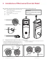
4 Installation of Mechanical Override Model
4.11 How to change lock cylinders
25. Loosen the set screw (01) to free the lever using Allen Key
(P1) (Approx. 1/4 turn). See fig 12 page 16
26. Remove the cap (E1) from the lever handle (A1) (see step
24, Fig. 18).
27. Insert key (L1).
28. Turn the key (L1) clockwise until it stops.
29. Release key (L1).
30. Use a small flat screwdriver to push in the lever catch (J1)
through the small hole underneath the lever handle (A1)
(Fig. 19).
Fig. 19
(A1)
(M1)
Small screwdriver
or equivalent tool
(L1)
31. Pull the lever handle (A1) off of the lock housing (be careful
not to lose the cylinder plug (C1)).
32. Replace the old cylinder with the new one in the lever han-
dle (A1). Only the same kind of cylinder with 2 grooves in a
cross in the end of the cylinder plug, could be used on the
locks. (Fig. 20)
Fig. 20
2 Grooves in cross
(A1)
(D1)


