


16
Saflok RT/RT Plus Installation Guide PK3720_T 04-19
4.5
Attaching the Lever Handle to the Lock
(with the key as shown in Fig. 6 & Fig. 7)
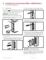
7. Fit the lever handle (A1) onto the drive tube (I1). It should
rest approximately 1/16" from the body of the housing. If
not, wiggle and jiggle key (L1) to align cylinder (D1) with
override shaft (K1) (See Fig. 8)
If the lever catch (J1) can’t be pushed close to the housing, it
is probably not pushed in. Push it in. (see fig 2 page 13)
If the lever catch (J1) is stuck, the override shaft (K1) is in
the wrong position. (see fig 2 page 13) The two small indents
(N1) on the cross of the override shaft (K1) must be vertically
aligned as in fig 2 page 13
(L1)
right-handed lock
Recess entry for
key in TOP Position
Recess entry for key in BOTTOM Position
left-handed lock
Fig. 8
(A1)
(L1)
(A1)
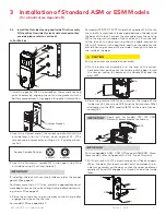
8. Press the lever (A1) firmly against the housing while turn-
ing the key (L1) counterclockwise (this applies to both
right-handed and left-handed locks) until it is in the hori-
zontal position. (Fig. 9)
Fig. 9
right-handed lock
left-handed lock
(Housing)
(L1)
(A1)
CAUTION
WARNING
IMPORTANT
If it is not possible to turn the key (L1) counter-clockwise
to complete this step, the spring washer (H1, see page 12)
may be too tense:
Hit the lever carefully with a rubber mallet to loosen the
spring washer (H1). (you may want to cover the lever handle
(A1) with a cloth or other material to protect the finish of the
metal)
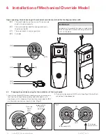
9. Remove the key (L1). The lock will look as shown in Fig.10.
right-handed lock
left-handed lock
Fig. 10
Gently check the rotation of the lever handle (A1). It should
easily rotate approximately 45º.
Troubleshooting:
Right-handed Lock: Turn the lever handle (A1) clockwise
without forcing it. If it stops at approximately 15º, it
was not assembled correctly as shown in step 6 (Fig.
6 & 7). Do not try to force it to turn. Release the lever
handle (A1). Insert the small screwdriver (M1, page 16)
into the small hole on the underside of the lever han-
dle (A1) and push in the lever catch (J1) see page 13.
Re-do steps 2, 3, 4 & 5.
Left-handed Lock: Turn the lever handle (A1) counter-
clockwise without forcing. If it stops at approximately 15º,
it was not assembled correctly as shown in step 6 (Fig. 6
& 7). Do not try to force it to turn. Release the lever han-
dle (A1). Insert the small screwdriver (M1, page 16) into the
small hole on the underside of the lever handle (A1) and push
in the lever catch (J1) see page 13. Re-do steps 2, 3, 4 & 5.
4 Installation of Mechanical Override Model


