31
Chapter 3
DDF7012 Installation and Setup
ANTENNA MOUNTING
Four antenna elements are used for mobile operation. At frequencies below 500 MHZ,
magnetically mounted quarter wave whips are used. These antennas must provide a good
coupling to the ground plane,and must be of exactly the same type. It is especially important
that the coaxes used have the same length. Precut antennas are provided that cover the 125 -
250 MHz band and the 250 MHz to 500 MHz band.
For frequencies above 500 MHz quarter wavelength "stubby" antennas are provided.
Note: T
o avoid damage to the input circuitry used in the RF summer, touch the antenna to the
ground plane before attaching the whips to the magnetic mounts.
It is important that the vehicle provides at least 1/4 wavelength of ground plane outboard of
the antennas.
Place the RF summer on the car with the cables oriented towards the rear of the car. Connect
the magnetic mount antenna cables to the corresponding TNC connectors on the RF
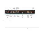
summer. (That is, the left front antenna to the left front connector, etc. as shown in Figure 18)
Locate the summer near the back of the car (the lid of the trunk or boot) so that the magnetic
mount antenna cables do not have excessive slack. Space the antennas between 1/8 and 1/4
wavelength apart on the car’s roof. Secure the four antenna cables together with nylon ties so
that they are not free to move around and touch the antenna elements. Route the control
and RF cables through a rear window. For mobile operation in the 700-1000 MHZ band, the
antenna with summer assembly should be mounted directly on top vehicle. This antenna
provides an extended ground plane, a wind shroud, and four stub type antennas built into
TNC connectors. Place the assembled RF summer/antenna in the center of the car roof. Be
sure to use the safety straps provided with the antenna as shown in Figure 19 below.
Summary of Contents for DDF7011
Page 1: ...USER S GUIDE DDF7011 AND DDF7012 USERS MANUAL ...
Page 2: ......
Page 6: ......
Page 24: ...18 DDF7011 and DDF7012 Users Manual User s Guide Figure 15 TU Antenna Mast Installed ...
Page 25: ...19 DDF7011 Installation and Setup Figure 16 THF Antenna Frame Installed on Mast ...
Page 28: ......
Page 29: ...23 23 CORE MODULE CONNECTIONS Figure 17 below shows the front panel of the Core Module ...
Page 30: ......
Page 31: ...25 25 Figure 19 Fixed Site Core front panel connections ...
Page 32: ......
Page 34: ......
Page 38: ...32 DDF7011 and DDF7012 Users Manual User s Guide Figure 20 VHF and UHF antenna arrangement ...
Page 40: ......
Page 41: ...35 Figure 22 Mobile core module connections ...
Page 42: ......
Page 44: ...38 DDF7011 and DDF7012 Users Manual User s Guide Appendix SPECIFICATIONS ...
Page 46: ......


