29
IN THIS CHAPTER
Getting Started ................................................................................................... 29
Antenna Mounting ............................................................................................ 31
Core Module Connections ............................................................................. 33
GETTING STARTED
As delivered the DDF7012 suite consists of the following
One Pelican case containing the core module
One Pelican case containing the antennas and all the accessories
One laptop computer case (optional)
Initial Setup
1)
Install the summer assembly and antennas on roof of the vehicle.
2)
Install the radio modem antenna on the roof of the vehicle.
3)
Install the GPS receiver on the roof of the vehicle
4)
Install the compass (optional) on the roof of the vehicle.
5)
Route all cables through a window opening in the vehicle. Do not route cables where
they can be crushed.
6)
Securely mount the yaw rate sensor (optional) anywhere within the vehicle. The wide side
of the sensor must be mounted parallel to the floor of the vehicle.
7)
Open the core module case.
8)
Connect the radio modem antenna to the TNC connector on the core module.
9)
Connect the direction finder antenna and control cables
10)
Remove the laptop computer from its case
11)
Connect the laptop power cable from the connector panel to the laptop computer
12)
Connect the Ethernet crossover cable between the laptop and the core module.
13)
Connect the GPS receiver to the core module.
14)
Connect the Yaw Rate sensor (optional) or compass (optional) to the core module
Chapter 3
DDF7012 INSTALLATION AND SETUP
Summary of Contents for DDF7011
Page 1: ...USER S GUIDE DDF7011 AND DDF7012 USERS MANUAL ...
Page 2: ......
Page 6: ......
Page 24: ...18 DDF7011 and DDF7012 Users Manual User s Guide Figure 15 TU Antenna Mast Installed ...
Page 25: ...19 DDF7011 Installation and Setup Figure 16 THF Antenna Frame Installed on Mast ...
Page 28: ......
Page 29: ...23 23 CORE MODULE CONNECTIONS Figure 17 below shows the front panel of the Core Module ...
Page 30: ......
Page 31: ...25 25 Figure 19 Fixed Site Core front panel connections ...
Page 32: ......
Page 34: ......
Page 38: ...32 DDF7011 and DDF7012 Users Manual User s Guide Figure 20 VHF and UHF antenna arrangement ...
Page 40: ......
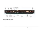
Page 41: ...35 Figure 22 Mobile core module connections ...
Page 42: ......
Page 44: ...38 DDF7011 and DDF7012 Users Manual User s Guide Appendix SPECIFICATIONS ...
Page 46: ......


