


96
MicroController Control System
Testing And Adjusting
System Tests and Adjustments
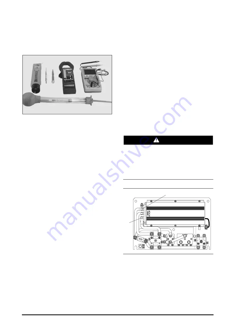
Test Equipment
There are various pieces of electric truck test
equipment that Daewoo recommends for all service
personnel. This equipment is available from a
number of world wide manufacturers and local
electronic suppliers. Contact your Daewoo dealer or
the factory for further recommendations.
Handheld Multimeter
A digital multimeter that measures DC voltage,
resistance, and has a diode tester, is required. It is
recommended that a high quality meter that is drop
protected, or comes with a drop proof case, be
purchased. Autoranging features, fast becoming an
industry standard, are convenient for the service
personnel, but are not required for servicing the lift
truck. A variety of miniature test leads, alligator clips,
and needle probes are also useful, and some of
these usually come with the multimeter.
Clamp-on Current Probe
The electric lift truck testing and adjusting procedures
require the measurement of average DC currents.
Currents in excess of 600 amps may be present, so
a clamp-on meter that will exceed this level is
required. It is also highly recommeded that a device
that has a voltage output, as well as a visible display,
be used. This makes viewing and adjusting currents
from the operator's seat possible. The jaws of the
current probe should be able to accept at least a
19mm (.75 inch) cable diameter.
Potentiometer Adjustment Tool -Trimmer
Available from most electronic suppliers, this
insulated tool allows for fast and easy adjustments of
potentiometers.
Hydrometer
Hydrometers are usually available from any battery
supplier. Battery maintenance is a crucial part of
maintaining the electric vehicle. The ability to
measure specific gravity and adjust the battery
discharge indicator to match battery manufacturers
specifications is an important part in the total
maintenance of the electric vehicle.
Discharging Head Capacitors
(HEAD CAP)
Battery voltage and high amperage are present.
Injury to personnel is possible. Disconnect the
battery and discharge the head capacitor (HEAD
CAP) before any contact is made with the control
panel.
Discharging Head Capacitor (HEAD CAP)
(1) Positive terminal. (2) Negative terminals.
1.
Disconnect the battery and discharge the head
capacitor.
2.
Put a 82 ohm, 80 watt resistor Part No.
929315, in position between the positive (1) and
negative (2) terminals. Hold the resistor in position
for 10 seconds. This will discharge the capacitor
below 5 volts.
WARNING
1
2
Summary of Contents for B20S-3
Page 3: ......