background image


MAN05MGO5


INSTRUCTIONS JIB CRANE SERIES GBA - GBP

15

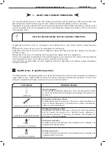
PICTOGRAMS USED TO INDICATE DANGERS

Warning danger from suspended loads being moved by the hoist.

MEANING

PICTOGRAM

Warning danger of crushing due to mechanical machine-parts in movement.

Warning danger of entanglement or dragging from machine-parts in motion 
(chains, wheels, etc.)

Signals the presence of live voltage and is fixed to electrical equipment
and on any structure which has live electrical voltage inside.

It is forbidden to transit, remain or manoeuvre under the suspended load.

Before putting the jib crane into service it is necessary:

•฀to฀read฀the฀technical฀documentation฀carefully;

•฀to฀find฀out฀about฀the฀functioning฀and฀the฀positioning฀of฀the฀emergency฀stopping฀devices;฀

•฀to฀know฀which฀safety฀devices฀are฀installed฀on฀the฀jib฀crane฀and฀where฀they฀are฀positioned;

Some activities to be carried out on functioning components (e.g. replacing a hoist chain) expose the operators to 
situations of danger, so staff must be authorised and properly trained regarding the operating procedures to follow, 
the dangerous situations that could occur and the correct methods for preventing them.

3.2

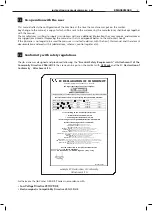
Norme generali di sicurezza

3.3

Safety symbols

In the manual pictograms are used to underline or bring attention to potentially dangerous situations due to residual 
risks, or to actions which must be performed obligatorily according to the safety procedures shown in this manual.

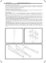
It is forbidden to touch the crane arm and the trolley/hoist in motion
or to stand in their path.

It is forbidden to carry out manoeuvres during maintenance phases
of moving machine-parts.

It is forbidden restart the hoist if the protections were not removed relocated.

It is compulsory to wear protection gloves.

Comply with the instructions as stated within the manual.

The preventive checking of chains, hooks, safety harnesses and
accessories used for lifting and monoeuvring is compulsory.

KMAN05MG05

Summary of Contents for GBA Series

Page 1: ...M A N 0 5 M G 0 5 INSTRUCTIONS JIB CRANE Column series GBA Wall series GBP ISTRUCTIONS installation use maintenance KM A N 05M G 05...

Page 2: ...INSTRUCTIONS JIB CRANE SERIES GBA GBP MAN05MGO5 INSTRUCTIONS JIB Crane Column series GBA JIB Crane Wall series GBP MAN05MG05 KMAN05MG05 KMAN05MG05 KMAN05MG05...

Page 3: ...Safety measures and instructions 17 3 5 1 Control devices 17 3 5 2 Safety and emergency devices 17 3 5 3 Warning and signalling devices List of labels 18 4 HANDLING INSTALLATION PUTTING INTO OPERATIO...

Page 4: ...tions of use 41 5 6 Contraindications of use 43 5 6 1 Use not intended and not allowed Foreseeable and unforeseeable inappropriate use 43 6 MAINTENANCE OF THE JIB CRANE 45 6 1 Safety precautions 45 6...

Page 5: ...ent possibly fatal Failure to follow the attached instructions can cause a situation of serious danger for the safety of the operator and for people in the vicinity Follow the instructions scrupulousl...

Page 6: ...UHVSRQVLELOLW WKDW WKH QDPHG PDFKLQH ULGJH FUDQH ZLWK KRLVW DQG WUROOH W SH 6XVSHQGHG 5HVWHG UDQH VWUXFWXUH 6LQJOH JLUGHU RXEOH JLUGHU 7 SH 6HULDO 1U HDU LE FUDQH UDFNHW UP ROXPQ 7 SH 6HULDO 1U HDU O...

Page 7: ...ty of the warranty is subject to the correct installation periodical checks and maintenance as in the instruction manual for installation use and maintenance which accompanies the machine as well as t...

Page 8: ...screw anchors or dowelling 2 1 3 The composition of the jib cranes The composition of the jib crane is relatively simple both in the column mounted version and the wall mounted one Both have a steel s...

Page 9: ...eel inside which the hoist carrying trolley slides The arm is fitted with one or two staybolts which support the shape and link it to the rising rotating tube This model features extreme lightness of...

Page 10: ...r in a special channel OUNDATION FRAME WITH LOG BOLTS This is supplied on request in the column mounted version for the fixing of the column itself to the base foundation plinth fig 6 RACKETS AND STAY...

Page 11: ...e following standards and principal technical regulations have been taken into account EN ISO 12100 2010 Safety of the machinery EN ISO 13849 1 2008 General principles for design EN 60204 32 2009 Safe...

Page 12: ...g clearance 4HE TYPE OF TRANSLATION manual or electric in relation to the characteristics of the mass to be moved and the type of arm already selected channel cantilever staybolted girder 4HE NATURE O...

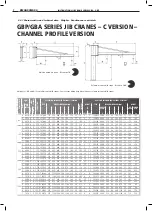
Page 13: ...beam h G M N 6 kg kg Size of jib crane Bracket Column H m Total Height base max KMAN05MG05 LIFTING CAPACITY ARM S SIZE OF JIB CRANE TROLLEY TYPE GBP SERIES WALL MOUNTED JIB CRANES C VERSION GBA SERIES...
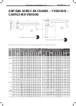
Page 14: ...by m Crane Under beam h G M N T IPE 6 kg kg Size of jib crane Bracket Column H m Total height base max 63 KMAN05MG05 GBP GBA SERIES JIB CRANES T VERSION CANTILEVER VERSION LIFTING CAPACITY ARM SIZE OF...

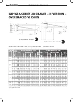
Page 15: ...255 1100 1240 300 1160 220 34 312 6 F Z 4 6 H40Z67 2980 513 210 1040 240 20 694 75 2 1600 KMAN05MG05 GBP GBA SERIES JIB CRANES H VERSION OVERBRACED VERSION LIFTING CAPACITY ARM SIZE OF JIB CRANE GBP S...

Page 16: ...the column itself to the foundation plinth is supplied on request 1 2 P C x 0 5 y 0 5 x 0 5 y 0 5 r i KMAN05MG05 FIXING SYSTEMS FOR JIB CRANES SIZE OF JIB CRANE A B C D E F Reactions kN Q2 2 95 5 9 2...

Page 17: ...expert qualified technicians who will evaluate the feasibility and formally assume the relative responsibilities KMAN05MG05 The fixing of the column using chemical bolts needs a scrupulous check of s...

Page 18: ...CIDENT PREVENTION IB CRANE OPERATOR Persons qualified to perform simple tasks that is the driving of the crane by use of the controls and the loading and unloading of the materials to be moved OPERATO...

Page 19: ...unctioning components e g replacing a hoist chain expose the operators to situations of danger so staff must be authorised and properly trained regarding the operating procedures to follow the dangero...

Page 20: ...Obligation to use protective glo ves during the phases of posi tioning of the harness and when moving the load by pushing it Risk from danger of crushing during the manoeuvring of loads suspended when...

Page 21: ...of the jib crane arm both in a clockwise and anti clockwise direction is activated manually with a pushing flexing of the load fig 8 3 5 2 Safety and emergency devices The manually rotated jib cranes...

Page 22: ...labels of the hoist and the trolley if present Legibility and conservation of the labels The labels and the data written on them must always be kept legible and must be periodically cleaned If a labe...

Page 23: ...sure that In case of damage or missing parts tell the courier note it on the accompanying document and notify DONATI SOLLEVAMENTI S r l within eight days of receiving the goods fig 11 M A N 0 5 M G 0...

Page 24: ...pictograms which give important information regarding the handling and transport mass handling points storage information etc fig 13 The items stored in the right way can be kept in a warehouse for a...

Page 25: ...rane and its accessories very carefully to the zone allocated for unloading and avoid oscillations swinging and dangerous unbalancing After handling check that the parts and the loads are intact and t...

Page 26: ...bility for use of the jib crane 4 3 Installation of the jib crane fig 16 The installation of the jib crane for the size of its operations can pose if not carried out correctly serious risks to the saf...

Page 27: ...e 3 adequacy of the section of the cable of the electrical power supply 4 that there is a suitable earthing system In the case of a jib crane with an arm with a section bar of laminated girder H or T...

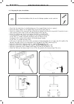
Page 28: ...the user and must be carried out by technical experts who judge the feasibility and take responsibility for this 1 Screw tight the low nuts 2 on the log bolts 1 leaving a threaded part up to have the...

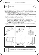
Page 29: ...foundation frame positioning the base plate 4 correctly and lining up the nuts 6 subject to the interposition of the related flat washers 5 fig 27 4 Check the verticality of the rotation axis as follo...

Page 30: ...who evaluate the feasibility and take on the related responsibilities 1 Screw up the nuts 1 on the four staybolts T and insert the contrast panels 2 fig 31 2 Assemble the two brackets the front one 3...

Page 31: ...re well settled in their respective housing of the front brackets fig 39 6 Using a mallet stick the level of the contrast boards 6 to the surface of the pillar fig 40 7 Tighten thoroughly the blocking...

Page 32: ...axis of the tube coincides with that of the plates and insert the rotation pivots 5 upper side pivot with 6 holes lower side pivot with 3 holes after lubricating them with grease fig 44 4 Block with...

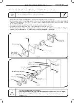
Page 33: ...N THE CASE OF THE COLUMN MOUNTED CRANE 4 Connect the electric cable 1 and the cable of line inserted previously in the column see 4 3 3 Assembly column Pos 2 to the terminals 4 contained in the connec...

Page 34: ...re 51b assembling the components 1 2 3 4 5 5 Position the isolating switch in the hole in the column connecting the relative electric cables finishing the assembly with the application of the yellow f...

Page 35: ...ist trolley on which you are working 1 Extract the channel trolley and the related hoist from any packing 2 Remove the split pin 1 and unscrew the suspension pivot 2 3 Insert the eyebolt or the suspen...

Page 36: ...ates which function for the intervention of the travel limit switches when installed with electric trolley These should be adjusted so they do not come into contact with the buffers Check there are no...

Page 37: ...g the instructions in this manual The installer must carry out the inspection and complete all the Inspection Report and complete the Suitability for use certificate After carrying out the empty test...

Page 38: ...the support structure and or the anchorings check the functioning of the emergency stop button which must stop and inhibit all the movements Any function of the hoist and or trolley must stop in the s...

Page 39: ...ined on a machine tool machined surfaces wheels pivots etc must be protected with antioxidant products transparent varnishes grease etc 4 5 1 Storage and conservation of parts s 3TRUCTURE eliminate tr...

Page 40: ...pushing to control the travelling trolley In all cases the rotation movement of the arm is activated manually with push training When it is controlled by the push button control panel the push buttons...

Page 41: ...e fig 56 with an uneven mass with respect to the centre of gravity with surfaces which are not resistant enough to withstand the pressure of the hold those which are classified as dangerous e g flamma...

Page 42: ...can be subjected to a risk which constitutes a danger for their safety health or psychophysical integrity It is necessary to inform the people potentially exposed that the jib crane operator does not...

Page 43: ...chine in particular he must strictly adhere to the specifications contained in this manual 5 2 5 The lifting capacity of the jib crane The lifting capacity of the jib crane in its original operative c...

Page 44: ...and visually check the balance of the mass being moved Avoid sharp or jolting movements which are very damaging to the stability of the load because of the dynamic effects which are generated Never li...

Page 45: ...F or 0 zero 5 4 Switching off at the end of use To shut down the crane at the end of work it is necessary to 7 93 follow the directions and instructions in the use and maintenance manuals and check th...

Page 46: ...lifted load 7 93 carry out the handling avoiding jogging 7 93 avoid combinations of handlings such as operating the lifting and the translation push buttons at the same time and be careful not to cau...

Page 47: ...2 use the crane for jobs other than those for which it was designed do not use it for other operations such as painting ceilings changing light bulbs a place to rest scaffolding on etc 6 2 lift unbal...

Page 48: ...one of the phases is lacking 6 2 perform sudden changes of direction during lifting travelling and rotation operations 6 2 press the control buttons on the push button panel repeatedly 6 2 modify the...

Page 49: ...tion regulations Unauthorised staff must be outside the work area during operations WARNING notes precede an operation which if not correctly carried out may cause damage to the crane and its componen...

Page 50: ...mable or toxic solvents petrol ether alcohol etc Avoid long periods of contact with solvents and inhalation of their vapours Avoid in particular use near open flames Before turning on the crane always...

Page 51: ...the specific operative and environmental characteristics s 4YPICAL MAINTENANCE ACTIVITIES mechanical regulation of the clearance of brakes and mechanisms test movements and mechanical regulation of th...

Page 52: ...of lifting system maintenance or of industrial handling s 4YPICAL MAINTENANCE ACTIVITIES mechanical adjustments of the safety devices calibrations and tests annual load test normal maintenance work af...

Page 53: ...to manage the measures necessary to put the jib crane and the hoist back into action and performance ability to write a maintenance intervention report s 1UALIFICATION REQUIRED Complete training of a...

Page 54: ...BAR s HECK WEAR ON AND HOOK BLOCK UNDERBLOCK s HECK WEAR OF WHEELS SPROCKET WHEELS GUIDE ROLLERS OF THE TROLLEY s 6ERIFY EFFICIENCY AND FUNCTIONALITY OF OVERLOAD SWITCH s 6ISUAL CHECK INSIDE SWITCHBOA...

Page 55: ...uarterly Annually General visual checks Verify good functioning General visual inspections Wear check Annual test 32 18 52 Hoist manual Hoist manual Hoist manual Hoist manual Hoist manual Hoist manual...

Page 56: ...the areas of contact If excessive wear is found substitute them during the check All screw bolts high resistance plugs and pins must be disassembled and carefully checked annually and so must the rel...

Page 57: ...iency of the wheels and the guide rollers of the channel trolleys fig 80 Annual check of the efficiency of the trolley buffers fig 81 Replace wheels and or guide rollers of the channel trolley if The...

Page 58: ...re visible Quarterly check of the efficiency of the brake of the rotation arm of the crane Quarterly check of the efficiency of the electric power supply Replace the clutch plates of the brake when th...

Page 59: ...e not highly specialised It is necessary to keep clean the following elements at regular intervals structure of the jib crane column bracket arm etc mechanisms of the jib crane pivots braking device e...

Page 60: ...be adjusted so as to guarantee the stability of the arm in any of its positions with a maximum load The braking is mechanical and is ensured by two pushed clutch plates which with adjusting screws wo...

Page 61: ...xyhydrogen flame saw etc All the components must be dismantled and scrapped having been reduced to small pieces so that none of them can reasonably be used again When the jib crane is scrapped their p...

Page 62: ...uate maintenance as described in this manual If necessary consult the jib crane components and spare parts manual The parts and components subjected to normal wear and tear or deterioration are to be...

Page 63: ...274 80 110 165 226 331 348 96 132 196 268 388 485 310 358 432 480 560 505 546 638 Bw Aw T01A20 T01B20 T02C20 T02D20 T03E20 T01A30 T01B30 T02C30 T02D30 T03E30 T01A40 T01B40 T02C40 T02D40 T03E40 T03F40...

Page 64: ...donati europe com www donati europe com DONATI Ltd Unit 40 Farriers Way Ind Est NETHERTON LIVERPOOL L30 4XL U K tel 44 0 151 530 1139 fax 44 0 151 525 6613 E mail sales donati co uk DONATI SOLLEVAMEN...

Reviews: