INSTALLATION, USE AND MAINTENANCE
GBA-GBP-CBE-MBE SERIES
40
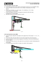
In the case of pillar crane series CBE
4. Connect the power cable (3) in the rotation control equipment (4) to the L1-L2-L3-N-EARTH clamps
5. Connect the rotation limit switch cable (5) to the clamps corresponding to the wiring
diagram.
6. Connect the flat festoon (6), power supply to the hoist/trolley, to the clamps
corresponding to the wiring diagram.
7. Connect the flat festoon cable (6) in the equipment on board the hoist to the clamps
corresponding to the wiring diagram.
8. Assemble and connect the isolator as shown on fig. 68
fig. 65
In the case of wall crane series MBE
4. Connect the power cable (1B) in the rotation control equipment (4) to the clamps L1
– L2 – L3 – N –
EARTH.
5. Connect the rotation limit switch cable (5) to the clamps corresponding to the wiring diagram.
6. Connect the flat festoon cable (6), power supply to the hoist/trolley, to the clamps corresponding to
7. the wiring diagram.
8. Connect the flat festoon cable (6) in the equipment on board hoist to the clamps corresponding to the
wiring diagram.
9. To connect the power cable (1B) to the clamps in the rotation control equipment.
fig. 66

