INSTALLATION, USE AND MAINTENANCE
GBA-GBP-CBE-MBE SERIES
32
Pillar assembling:
On a
foundation frame
(plinth):
1. When the plinth has solidified, remove the protection of the bolt threading and check that the high nuts
unscrew without forcing, then remove them and the washers.
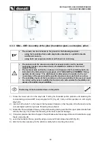
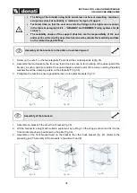
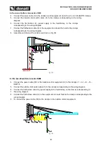
2. Where required insert the power supply cable 1 in the column positioned on the ground and let it
protrude from the hole located at the top of the column based on the following lay-out positions:
a. In the case of cable 1 that protrudes from the pipe set up in the plinth, directly insert the cable in
the column until reaching hole 2 located at the top of the column (fig. 27)
b. In the case of cable 1 coming from the outside, insert it into the column using the specific grommet
3 located at the base of the column, until reaching hole 2 at the top (fig. 28)
3. Erect the column without arm, lifting it in the upper part with suitable equipment after having slung it as
indicated, mount it on the foundation frame positioning base plate 4 correctly and approaching the nuts
6 after placing the relative flat washers 5 (fig. 29).
On a
counterplate with chemical bolts
:
1.
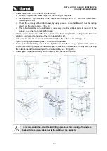
Once the counterplate has been fixed, push the power cable 1 into the pillar on the ground and through
the hole at the top of the pillar, according to the following layout: if the cable 1 comes from outside,
push it into the pillar using a suitable fairlead 3 placed at the bottom of the pillar, until it reaches hole
2 at the top (fig. 28)
2.
Set up the pillar without the arm, lifting it by the upper part with appropriate equipment having put it in
the sling as shown, assemble it on the counterplate positioning the base plate 4 correctly and secure
it using the special Kit supplied with the counterplate (fig. 30) (proceed with step 4)
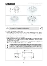
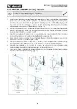
4. Check the verticality of the rotation axis as follows:
a. Remove the protective plastic plugs from the housing of the pivots
b. Insert the pivots
7
provisionally in their respective housing (see 4.3.5
”)
c. Check the verticality of the rotation axis, by using a level
L
and a bar which must be resting directly
on the rotation pivots
7
d. Perfect levelness can be obtained, if necessary, by inserting 8 appropriate spacers (not part of the
supply, in correspondence with the stay bolts, under the base plate (fig. 32).
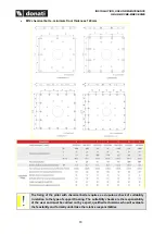
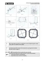
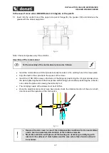
5. Stably screw the 6 nuts using a torque wrench, applying the clamping couples (see table on page 19)
based on the diameter of the log bolts/bolts, checking the nuts afterwards for unscrewing with the
relative safety nuts 9 (fig. 33).
6. For correct tightening in torque of the nuts/bolts at the bottom of the column all of the nuts/bolts need
to be brought into contact with the plate applying a light torque in order to prevent free movement.
Once in this situation, using a torque wrench, tighten the nuts in torque (see the nuts/bolts clamping
table on page 9 for the correct value) following the shown cross pattern (fig. 34) and being careful that
the column does not lose its vertical alignment. It is recommended to tighten in two steps: the first at
70% of the clamping couple and the second at 100%.
7. Once the bolts are tightened, control and, if needed, fix the paint around the bolts in order to avoid
possible corrosion.

