background image

INSTALLATION, USE AND MAINTENANCE 

GBA-GBP-CBE-MBE SERIES 


15 


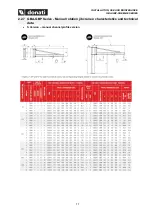
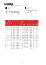
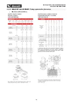
H Version 

– Manual overbraced version 


Summary of Contents for CBE Series

Page 1: ...JIB CRANE MANUAL AND ELECTRIC ROTATION PILLAR GBA CBE SERIES WALL GBP MBE SERIES USE INSTRUCTIONS INSTALLATION USE MAINTENANCE MARCH 2022 KMAN55MG01 Translated from the original Italian instructions...

Page 2: ......

Page 3: ...ranes 16 3 SAFETY AND ACCIDENT PREVENTION 19 3 1 Authorised operator qualifications 19 3 2 General safety regulations 20 3 3 Safety symbols 20 3 4 Warnings on residual risks 21 3 5 Safety devices and...

Page 4: ...52 5 2 4 Operator 52 5 2 5 Jib crane capacity 53 5 2 6 Manoeuvres lifting trolley traverse and arm rotation 53 5 2 7 Safety devices 54 5 3 Activating the jib crane 54 5 4 Deactivating at the end of wo...

Page 5: ...ent documentation should be requested directly from the manufacturer by quoting the code of this manual The manufacturer retains the material and intellectual rights of this publication and forbids th...

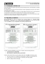
Page 6: ...tation declarations diagrams test logbook etc 1 4 Regulatory compliance GBA CBE GBP MBE jib cranes are designed and produced following the Essential Safety Requirements of Attachment I of the Communit...

Page 7: ...ticular always operate within the limits of use of the jib crane always perform a constant and diligent maintenance assign use of the machine to operators with a proven capacity adequately instructed...

Page 8: ...anual push action of the load using the circular area below limited by the rotation radius of the arm 2 1 2 Installation restrictions The GBA CBE pillar mounted jib cranes are intended to be fixed to...

Page 9: ...f pressed steel fixed to the wall or anchored to a pillar using staybolts or screws it acts as a support to the arm and allows it to rotate fig 4 The rotating arm The arm rotating around its own axis...

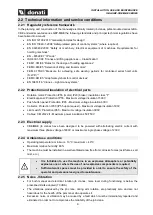
Page 10: ...all mounted jib crane for the connector between the line and the festooned cable The distribution of energy uses festoon cable which does not spread flames generally of the flat type sliding on suitab...

Page 11: ...e GBA CBE pillar mounted version and the GBP MBE wall mounted version are designed according to the conception of the modular components which put together in relation to commercial needs as well as t...

Page 12: ...ntegral with the arm which it powers Progressive starting up and braking are ensured by a frequency inverter powered with alternate monophase current with voltage at 230 V The limit switch to limit th...

Page 13: ...rotection IP65 Maximum voltage insulation 600V Collector Protection IP00 IP55 upon request Maximum voltage insulation 500V Limit switch Protection IP65 Maximum voltage insulation 300V Cables CEI 20 22...

Page 14: ...cate or not determines by its positioning the choice of the most suitable handling lifting and travel speeds In some cases it is indispensable to use hoists with two speeds with a slow positioning spe...

Page 15: ...INSTALLATION USE AND MAINTENANCE GBA GBP CBE MBE SERIES 11 2 2 7 GBA GBP Series Manual rotation jib cranes characteristics and technical data S Version manual channel profile version...

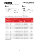
Page 16: ...INSTALLATION USE AND MAINTENANCE GBA GBP CBE MBE SERIES 12 T Version Manual Underbraced version...

Page 17: ...INSTALLATION USE AND MAINTENANCE GBA GBP CBE MBE SERIES 13 H Version Manual overbraced version...

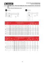
Page 18: ...INSTALLATION USE AND MAINTENANCE GBA GBP CBE MBE SERIES 14 2 2 8 CBE MBE Series Electrical rotation jib cranes characteristics and technical data T Version Manual Underbraced version...

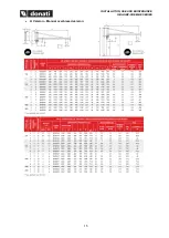
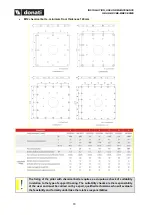
Page 19: ...INSTALLATION USE AND MAINTENANCE GBA GBP CBE MBE SERIES 15 H Version Manual overbraced version...

Page 20: ...INSTALLATION USE AND MAINTENANCE GBA GBP CBE MBE SERIES 16 2 2 9 GBA GBP and CBE MBE Fixing systems for jib cranes Brackets and foundations...

Page 21: ...bolts minimum floor thickness 170mm The fixing of the pillar with chemical bolts requires a scrupulous check of suitability in relation to the type of support flooring The suitability checks are the...

Page 22: ...f the pillar with chemical bolts requires a scrupulous check of suitability in relation to the type of support flooring The suitability checks are the responsibility of the user and must be carried ou...

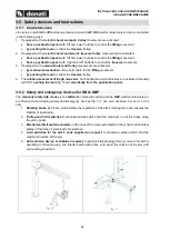
Page 23: ...d in this chapter in order to prevent the occurrence of hazardous situations 3 1 Authorised operator qualifications To better define the field of operation and the consequent undertaking of responsibi...

Page 24: ...IN THE MANUAL TO HIGHLIGHT HAZARDOUS SITUATIONS PICTOGRAM MEANING Risk of being crushed during handling of suspended loads in the case of exposure of the operator or other personnel in the zones areas...

Page 25: ...ty by complying with the instructions contained in this manual The rope and hook must be checked periodically Risk of being drawn in and or crushed following contact with the arm in rotation and or wi...

Page 26: ...ib crane arm both clockwise and anticlockwise is activated manually with P T pushing the load fig 10 or electrically from the pushbutton panel 3 5 2 Safety and emergency devices for GBA GBP The manual...

Page 27: ...request mechanical catches which limit the maximum rotation of the arm 4 Anticollision device available on request avoids any crash between 2 or even more jibs operating in a same area or prevents fro...

Page 28: ...em If a plate deteriorates and or is no longer legible including just one of the informational items shown it advisable to request another one from the manufacturer quoting the data contained in this...

Page 29: ...onally qualified personnel with a specialisation in assembling industrial plants with an electromechanical background equipped with work equipment and personal protection equipment in compliance with...

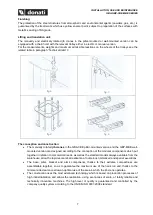
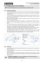
Page 30: ...special packaging or protections are excluded from the supply unless they are contained in the contract If necessary the packaging can include signs and pictograms that provide important information...

Page 31: ...t show any indication of their weight and can be handled by hand Sling the crane parts with suitable equipment in order not to damage the painted surfaces fig 15 o for columns and arms use stay bolts...

Page 32: ...ssembly of industrial plants Lifting and overhead placement of crane parts must be performed by installers equipped with o adequate and suitable personal protection equipment e g helmet gloves safety...

Page 33: ...es or operating machines are present fig 19 4 Verify the suitability and correct operation of the mains fig 20 a correspondence of the line voltage with the voltage required for the motors b presence...

Page 34: ...ponsibility of the user and must be carried out by expert qualified technicians who will evaluate the feasibility and assume the relative responsibilities Positioning of the foundation frame in the pl...

Page 35: ...e Once it has been embedded the work time when the bars need to be positioned and the time in which it is necessary not to work in order to let it harden completely are specified on the instruction b...

Page 36: ...t by the upper part with appropriate equipment having put it in the sling as shown assemble it on the counterplate positioning the base plate 4 correctly and secure it using the special Kit supplied w...

Page 37: ...again to take up any play due to settlement of the plinth Donati Sollevamenti SRL shall not be held liable for any fixings other than those indicated in fig 29 and fig 30 4 3 4 GBP MBE Assembly of th...

Page 38: ...the four staybolts T and insert the contrast panels 2 fig 35 2 Assemble the two brackets the front one 3 and the back one 4 for the fixing of the upper part of the bracket in such a position to obtain...

Page 39: ...ast boards 6 checking that the centring crowns 7 are well settled in their respective housing of the front brackets fig 43 6 Using a mallet stick the level of the contrast boards 6 to the surface of t...

Page 40: ...time that the clutch plate 2 and the pressure plate 3 fit into the lower part fig 47 3 Insert the tube between the plates 4 until the rotation axis of the tube coincides with that of the plates and in...

Page 41: ...TCEI M10 screws in the holes of the flange by positioning the 2 longer screws above the plate tightening them with their respective self blocking nuts and then positioning the 2 shorter ones under th...

Page 42: ...430 490 590 650 125 360 430 430 490 590 650 250 360 430 500 530 590 650 500 400 460 460 530 620 690 800 690 1000 400 460 490 560 620 1 Trolley block 2 Fixing bolts Before inserting the trolley block...

Page 43: ...illar mounted crane 4 Connect the electric cable 1 and the cable of line inserted previously in the pillar see 4 3 3 GBA CBE Assembly of the pillar foundation plate counterplate pillar Pos 2 to the te...

Page 44: ...ist to the clamps corresponding to the wiring diagram 8 Assemble and connect the isolator as shown on fig 68 fig 65 In the case of wall crane series MBE 4 Connect the power cable 1B in the rotation co...

Page 45: ...ecessary to operate on the limit switch releasing momentarily the cam of the contact in question Get out of the anomalous position with the opposite control to that of the operation Restore the origin...

Page 46: ...aller assigned by the user must Install in the immediate vicinity of the crane a line switch protected against short circuits showing its function with the appropriate label Have earthing connected to...

Page 47: ...the hoist in the trolley plate 3 or in the brake beam 4 respectively when using a simple or double trolley 4 Put back the pivot 2 and put the split pin back in place 1 5 Position the hoist trolley uni...

Page 48: ...he hoist trolley unit on a pallet and lift this until the leading height of the head of the channel section is reached 6 Working at a height insert the preassembled lifting unit in the channel section...

Page 49: ...round Check that the matching parts are present and working for tripping the traverse limit switches if the installation is with an electric trolley Adjust them to prevent contact with the buffers Mak...

Page 50: ...of the crane plate plus an overload factor of 1 1 load equal to 110 of rated load The static tests are performed with an overload factor of 1 25 load equal to 125 of the rated load All the tests must...

Page 51: ...ty x 1 1 being careful to position the hook vertically to avoid oblique pulling slowly tension the sling to avoid tugging perform the load tests using the slow speed if available lift the load and sto...

Page 52: ...erform the following operations Structure eliminate traces of lubrication from the structure and the trolley beam go over the hole threading and eliminate any grease residue cleaning the matching surf...

Page 53: ...ng movement from a pushbutton panel with right and left buttons to control the traverse movement If the crane is equipped with a manual hoist and trolley movements are activated by mechanical activati...

Page 54: ...e to their chemical and physical characteristics have been classified as hazardous for example flammable explosive radioactive etc materials toxic or handful materials or products if not handled in sp...

Page 55: ...ed intensify the maintenance cycles In the presence of flames and or heat greater than the allowed temperatures With the risk of fire or explosion where the use of anti explosion and or fireproof comp...

Page 56: ...ng use cleaning maintenance and repair disassembly dismantling and demolition The operators need to be persons suitable for the work and mentally and physically able to meet the needs connected with t...

Page 57: ...load At the end of handling carefully place the load and release the hoist hook During lifting manoeuvres the operator must avoid putting the hook on the ground or on the loads to lift to prevent the...

Page 58: ...able as operating stops The safety devices when excluded from the DONATI SOLLEVAMENTI S r l supply must be installed by the customer It is prohibited to put the jib crane into service and or affix the...

Page 59: ...lifting hook from the slings used to handle the load 3 Lift the hook where possible to a height not under 250 cm i e so that it does not create disturbances and danger for the movement of people and...

Page 60: ...aged or missing its spring catch ALWAYS check the suitability and efficiency of the slings ropes chains bands etc ALWAYS check that the track for movement of the trolley is installed at a height which...

Page 61: ...est any observations related in particular to the hook chains brakes and limit switch fig 82 fig 83 fig 84 fig 85 fig 86 fig 87 5 6 Use contraindications The use of the jib crane for unpermitted manoe...

Page 62: ...s intended avoid using it for other operations for example painting ceilings changing light bulbs as a support for scaffolding etc NEVER lift unbalanced loads NEVER swing the load or the hook during t...

Page 63: ...ttings of the safety devices limit switches clutch device fig 94 NEVER perform temporary repairs or reset interventions not in compliance with the instructions NEVER use non original spare parts or th...

Page 64: ...ly performed may cause an operator accident Pay attention to the following WARNING NOTES during the maintenance phases Before restarting the jib crane after a fault it must be carefully inspected and...

Page 65: ...e not been left on the crane Always use protective gloves during maintenance operations All the accessible moving parts with the sole exception of the chain and subblock block are protected against ac...

Page 66: ...and hook and performance of simply performed maintenance activities which do not require overhead interventions e g hook thrust bearing lubrication Required technical knowledge knowledge of the functi...

Page 67: ...electrical components and safety devices used in the hoist limit switch brakes etc knowledge of average difficult electrical control and adjustment techniques replacement based on the original diagra...

Page 68: ...ence in lifting and handling systems Electrical technician Typical maintenance activities electrical adjustments of safety devices calibrations and acceptance tests annual load tests routine maintenan...

Page 69: ...o a minimum 2 A promptly executed repair avoids additional deterioration of the crane or its components 3 Use original spare parts and products 4 The following instructions need to be complied with fo...

Page 70: ...erations handled by the operator assigned to crane use general visual inspections functional tests with testing of motors limit switches clutch device brakes with no load stop button and other functio...

Page 71: ...ts Visual inspection Check wear and efficiency Hoist manual Lifting hook Visual inspection and check spring catch Check wear and efficiency Hoist manual Loading nut Chain guide Block return Check wear...

Page 72: ...tability and repair any damage if necessary The brackets composed of plates and pin that form the hinged parts are subject to wear since they are mobile and swinging parts subject to radiating frictio...

Page 73: ...wheel has wear of 5 mm The rolling diameter of the guide roller has wear of 2 mm If even just one wheel needs to be replaced to obtain the best operating guarantee and duration it is advisable to repl...

Page 74: ...he efficiency of the power cable make sure there are no worn patches cuts abrasions or other alterations of the protection sheathing Check the tightening of the conductors power cable and their termin...

Page 75: ...materials Clean by removing any foreign and dirty substances with vacuums absorbent cloths etc Dry any excess grease and or oil on the parts Accurate management of the jib crane mechanism lubrication...

Page 76: ...the arm The clutch plates which are asbestos free are subject to wear in relation to the intensity of service and when after a period of use there is a tendency of the arm to take up preferred positio...

Page 77: ...ntervention of specialised or specifically trained personnel or the manufacturer s technical personnel is necessary 6 5 3 Decommissioning If it is not possible to repair the jib crane decommission it...

Page 78: ...ancelling the warranty may compromise the correct operation of the jig crane and or its components 8 CONTROL BOOKLET To demonstrate the correct performance of all of the test and maintenance activitie...

Page 79: ......

Page 80: ...riportate sono di propriet della Donati Sollevamenti S r l pertanto ne vietata la riproduzione divulgazione ed utilizzo senza esplicito permesso Donati Sollevamenti S r l declina ogni responsabilit p...

Reviews: