


Installation, Operation and Maintenance Manual
Unimaster Dust Collectors – Series UMA 40-750
17
INSTALLATION
UMA 40H, UMA 40MM H, UMA 70H, UMA 100H, UMA 150H, UMA 250H,
UMA 450H and UMA 750H
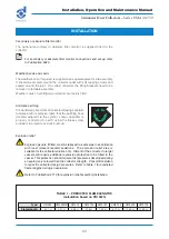
These collectors are supplied fully assembled.
When the collector is fitted with an explosion relief assembly, the
explosion relief area is suitable for the collector volume only. Additional
protection may be required when mounting onto other vessels.
1 Using the sealant provided, apply two beads of sealant to the site seating
flange, one each side of the fixing holes, as shown in figure 11 (if required,
details of mounting flange fixing positions are provided in dat
a
sheet of
UMA 40,UMA 70-250,UMA450 and UMA 750).
2 For UMA 40 and 40MM collectors, lift the collector using the fork lifting
method, onto the site seating flange.
For UMA 70-750 collectors, lift the collector using either the four-point lifting
method or the fork lifting method, onto the site seating flange.
3 Secure the joint with fixings to suit the application and remove excess
sealant.
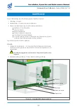
When the UMA 750H is supplied with the optional secondary or absolute filter, the
acoustic diffuser is supplied separately and should be assembled as follows:
1 Remove lifting brackets from the collector.
2 With the aid of a colleague, lift the acoustic diffuser onto its back, taking care
not to damage the paintwork.
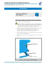
3 Using the sealant supplied in the fixing pack, seal all around the underside
of the seating flange (see fig. 9).
4 Lay the acoustic diffuser down so that the lifting brackets are uppermost.
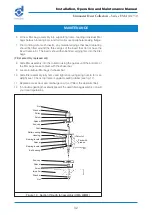
5 Using the four-point lifting method, lift the acoustic diffuser into position on
top of the fan section, so that the diffuser outlet is at the front, right-hand
corner of the top plate (see fig. 10).
6 The acoustic diffuser can now be fixed in position using M10 bolts and
washers at the sides, and self-tapping screws at the front and rear.
Unimaster hopper type
dust collectors


