


BioClass HC
48
22
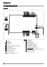
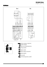
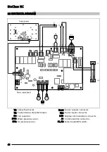
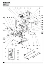
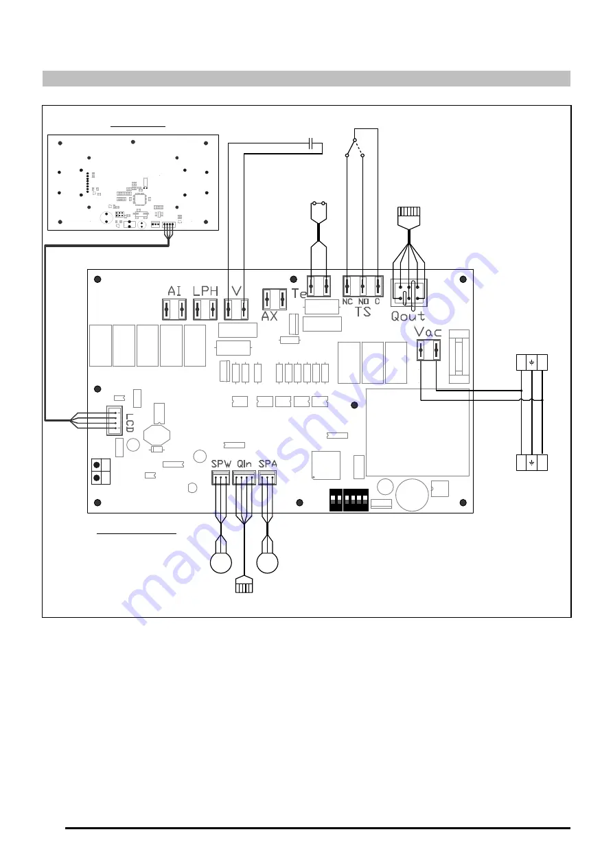
ELECTRICAL DIAGRAM
J4
J1
2
1
+
A
-B
J12
2
1
C
1
2
TS
TE
Q
in
Q
out
SPW
C
V
SPA
1
2
S1
S2
4
3
2
1
ON
ON
B
lu
e
B
ro
w
n
Power supply board
Display board
P
in
k
B
la
ck
B
ro
w
n
B
lu
e
W
h
it
e
G
re
e
n
G
re
e
n
Ye
llo
w
/G
re
e
n
B
ro
w
n
B
lu
e
TS:
Safety thermostat.
TE:
Fuel entrance safety thermostat.
Cv:
Fan capacitor.
SPW:
Water pressure sensor.
SPA:
Air pressure sensor.
Qout:
Burner outputs connector.
Qin:
Burner inputs connector.
LCD:
Display communication connector.
J4:
Communication connector.
S1, S2:
Boiler model DIP-switch.


