background image

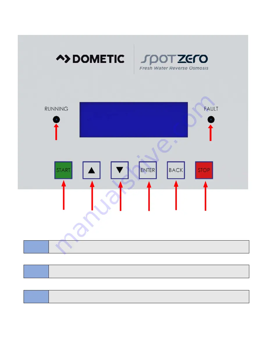
LCD Touchpad Navigation 


NOTE 

START Button NOT REQUIRED for standard system operation. System will turn on when 

sufficient feed flow recognized. 

NOTE 

Pressing START will resume normal operation of the system if the stop button has been 

pressed and there is sufficient feed flow. 

NOTE 

Pressing STOP button will halt all system operation until power is cycled to the unit or the 

START button is pressed when proper feed flow is present. 

LED light will illuminate 

blue when running 

LED light will illuminate 

red when there is a 

system fault 

Move Cursor 

or Selection 

Up 

Move Cursor 

or Selection 

Down  

Confirm 

Selection or 

Change  

Return to 

Previous 

Screen  

Stop System 

Operation 

Start System 

Operation 

34

Summary of Contents for SPOTZERO SZIII 2000

Page 1: ...USER MANUAL INSTALLATION GUIDE SZIII 2000 3000 www spotzerowater com ...

Page 2: ... 12 SZIII One Line Flow Diagram 13 PRE FILTRATION 14 Pre Filtration Plumbing 14 Overboard Connection 15 Product to Tank Connection 15 Feed From Watermaker 16 Membrane Supply 16 Membrane Return 17 Membrane Product 17 Operation and Maintenance 18 Operation Specifications 19 Feed Water Specifications 19 System Standard Operating Parameters 20 TEMPERATURE CORRECTION FACTORS FOR MEMBRANE PRODUCTION 21 ...

Page 3: ...II Consumable Items 31 32 Initial Startup 32 LCD Touchpad Navigation 34 SZIII LCD Menu Tree 35 STANDARD OPERATION 3 Performing a Freshwater Flush Bacteriostatic Remineralizer Troubleshooting 4 Troubleshooting Guide 4 Abnormal Product Flow IS MY SYSTEM WORKING PROPERLY 4 TDS REJECTION Membrane Cleaning Procedure SZIII System Specification and Parts 4 Bacteriostatic Remineralizer Assembly Drawing 4 ...

Page 4: ... Introduction 4 ...

Page 5: ...HER ASSOCIATED INFORMATION FOR FUTURE REFERENCE AND FOR NEW OPERATORS OR QUALIFIED PERSONNEL NEAR THE SYSTEM Acronyms and Definitions Safety The safety section of this User Manual outlines the various safety headings used throughout this manual s text and are enhanced and defined below DO NOT UNDER ANY CIRCUMSTANCES REMOVE ANY CAUTION WARNING OR OTHER DESCRIPTIVE LABELS FROM THE SYSTEM NOTE INDICA...

Page 6: ...ighly concentrated solution For example a freshwater solution will naturally want to mix with a saltwater solution Reverse Osmosis To reverse this process work is put into the system using a pump The pump causes pressure to build up on the saltwater side of the membrane This pressure forces water across the semi permeable membrane The membrane is designed to allow the water molecules to pass while...

Page 7: ...w GPM LPM 1 3 7 1 3 7 Connections Feed Inch Hose Hose Product Inch QC 9 5mm QC 9 5mm Concentrate Inch QC 2 7 mm QC 2 7 mm Membranes Membranes PerVessel 1 1 Membrane Quantity 1 2 Membrane Size 4041 4041 Pumps FW Pressure PumpType Vane Vane FW RO Motor Amps 5 1 5 1 Electrical Voltage 115V or 230V 50 60Hz 115V or 230V 50 60Hz Amp Draw 6 6 System Dimensions Width x Depth x Height inch cm 17 5 x 12 9 x...

Page 8: ...Installation and Commissioning 8 ...

Page 9: ...58 Adapter 5 8 QC Stem to 3 8 QC 2 H5089 Install Kit 5 16 Hardware Set 1 B0013 Elbow 3 8 QC Stem to 3 8 QC 4 B0010 Elbow 1 2 QC Stem to 1 2 QC 4 E1018 Wrench for Big Clear 4 5 10 20 1 B5001 Locking Clip 3 8 Install Kit 20pc 1 B5002 Locking Clip 1 2 Install Kit 20pc 1 H5065 Lubricant Silicone 6 grams 1 B0043 Ball Valve 3 8 QC 1 MN1003 SZIII Manual 1 AE0004 Bacteriostatic Remineralizer Assembly 1 B0...

Page 10: ...be square and remove burrs and sharp edges Ensure the outside diameter is free of scoremarks For soft or thin walled tube we recommend the use of a tube insert Push the tube into the fitting to the tube stop To disconnect ensure the system is depressurized push the collet square against the fitting With the collet held in this position the tube can be removed CAUTION ANY RESTRICTIONS OR BLOCKAGE I...

Page 11: ...le with the requirements of the unit and capable of supplying the specified power for the SZIII unit you are installing For clarification SZIII models that have a part number of 9610003810 or 9610003807 are the 115 volt configuration and units with a part number of 9610003808 or 9610003807 are 230 volt units PC BOARD DIP SWITCH SETTINGS NOTE IT IS RECOMMENDED THAT A QUALIFIED ELECTRICIAN WIRES YOU...

Page 12: ...let Source FWF IS EGND EGND L2 BP L1 L2 HP L2 TDS TL PO PP CP PF PI RF CF BLU WHT RED BLK WHT BLK RED BLK WHT RED GRN WHT GRN BLK RED BLK RED BLK RED BLK RED BLK RED B A GND GND 24VDC B A GND GND 24VDC 12 ...

Page 13: ...13 ...

Page 14: ...mes clogged and the water flow to the pump is reduced or interrupted cavitation will occur and damage the pump A Spot Zero system must be operated on filtered water only Make sure to read all labels and instructions on the filters before installation and use Pre Filtration Plumbing Plumb the feed water from the dock into the pre filter inlet fitting using a customer supplied 1 NPT connection From ...

Page 15: ...run WARNING SPOT ZERO SYSTEMS REQUIRE THAT THE OVERBOARD MUST NEVER BE CLOSED OR OBSTRUCTED WHILE SYSTEM IS OPERATIONAL CLOSING OR OBSTRUCTING THE OVERBOARD FLOW ON THE SYSTEM MAY CAUSE PERMANENT DAMAGE TO THE SYSTEM WARNING SHIPS FRESHWATER TANK MUST BE VENTED PROPERLY TO AVOID BACK PRESSURE ON THE SYSTEM FAILURE TO DO SO MAY CAUSE PERMANENT DAMAGE TO THE SYSTEM AND OR RESULT IN UNDERPERFORMANCE ...

Page 16: ...tank If the bacteriostatic remineralizer is not section on the bacteriostatic remineralizer on pg 41 to see its purpose Feed From Watermaker FEED FROM Always install a three way valve in line with this so the water can be diverted to the ships fresh water tank if required Membrane Supply QC tubing from the assemblies From Watermaker 16 ...

Page 17: ...Membrane Return Membrane Product assemblies Membrane Assembly 17 ...

Page 18: ...Operation and Maintenance 18 ...

Page 19: ...owed for the membranes used in this system CAUTION The rated production will have to be corrected for temperature of the inlet water when determining pg 21 for an example on correcting the rated flow rate WARNING DO NOT OPERATE THE SYSTEM BEYOND THE RATED PRODUCTION RATE DOING SO CAN CAUSE SCALING OR FOULING OF MEMBRANES NOTE It is very important to meet the minimum feed water requirements Failure...

Page 20: ...re Minimum psi bar Pre filter Inlet P r e s s u r e Maximum psi bar Pre filter Outlet Pressure Minimum psi bar Pre filter Outlet Pressure Maximum psi bar SZ ZTCII XZ FW RO SERIES GPD 2000 1 4 5 3 1 0 3 8 2 0 7 6 4 4 16 7 150 10 3 150 10 3 15 1 85 4 15 1 85 4 GPD 3000 2 0 7 5 1 0 3 8 2 0 7 6 5 18 9 150 10 3 150 10 3 15 1 85 4 15 1 85 4 SZ HD XZ HD FW RO SERIES GPD 4000 2 7 10 2 1 5 5 7 2 0 7 6 6 2 ...

Page 21: ...he unit will either produce more or less product than its rated production at 77 F To find the temperature correction factor TCF the table below may be used Simply divide the listed standard system flow rate at 77 F by the temperature correction factor The result is the permeate flow at the desired temperature See example below Refence F C x 9 5 32 Corrected Flow Rate Measured Flow Rate TCF Feed W...

Page 22: ...igned to reject up to 99 of Total Dissolved Solids meaning at best only approximately 1 of dissolved solids do not pass through the membrane To calculate the rejection use the following formula Rejection Feed TDS Product TDS Feed TDS x 100 Example 95 300 15 300 x 100 The amount of product water recovered for use is expressed as a percentage To calculate the recovery use the following formulas Reco...

Page 23: ...ration Guidelines Avoid any abrupt pressure or crossflow variations on the spiral elements during start up shut down cleaning or other sequences to prevent possible membrane damage During start up a gradual change from a standstill to operating state is recommended as follows Feed pressure should be increased gradually over a 30 60 second time frame Crossflow velocity at set operating point should...

Page 24: ...plates in place with a 5mm Allen head wrench 3 After the bolts have been removed remove both retainer plates by sliding them towards the center to free them from the grooved ring seat 4 Remove the end hub from the pressure vessel This may take a bit of force to do as the end hub may have come tightly pressed to the walls of the vessel A pair of pliers may be used to pull on the hub until it is rel...

Page 25: ...xamine the brine seal and permeate tube for nicks or cuts Replace the O rings or brine seal if damaged 4 Lubricate the Brine Seal with a food grade lubricant We recommend Molykote 111 Compound 5 Installthemembrane element so the brine seal will be locatedatthesupplysideofthevessel CAUTION Removing the membrane in the orientation shown above can only be done if you will replace it with a new membra...

Page 26: ...tart Up the system please refer to the Initial Start Up section of this manual on pg 32 WARNING THE BRINE SEAL MUST BE IN THE SAME POSITION FOR EACH MEMBRANE ELEMENT HOUSING THE BRINE SEAL IS A RUBBER SEAL THAT PROTRUDES ON ONE SIDE OF THE MEMBRANE AND IS ALWAYS ON THE FEED SIDE OF THE MEMBRANE ELEMENT CAUTION Wet membranes are shipped in a preservative solution The membranes must be flushed for a...

Page 27: ...age chemical bottle to make the storage solution This should make approximately 5 gallons of solution 5 Pour the 5 gallon solution into the empty bucket that the tube runs are placed in 6 Use an auxiliary pump to circulate the solution into the unit This pump should be hooked up into the Once the auxiliary pump is running turn on the system and recirculate the solution throughout the system Comple...

Page 28: ...aner bottle 4 After 30 minutes of flushing power off the unit 5 Reconnect the product to tank connection and fully open the recycle and concentrate valves by rotating counterclockwise 6 Once the system is ready for use the concentrate and recycle flows will have to be dialed in as instructed in the operating section WARNING ENSURE ALL OF THE PRODUCT WATER DURING THE 30 MINUTE FLUSH IS BEING DISCAR...

Page 29: ...LLDPE hose from the LLDPE hose from the on the unit 5 A solution must be made to winterize your unit A 5 gallon 50 50 ratio of the following two ingredients must be mixed with one bottle of the Spot Zero chemical cleaner a Propylene glycol which can be purchased at most hardware or automotive stores b Distilled water or product water from your Spot Zero unit c Membrane storage chemical part 252404...

Page 30: ...e LCD display assembly To wire up a remote screen follow the procedure below Mount the remote keypad assembly in the desired location Run the supplied four wire cable for the remote screen from the mounting location to the unit Make sure that the unit is off and disconnected from the power source The front cover of the unit s electrical box will have to be opened and the wires will need to be hook...

Page 31: ...ediment Pre Filter Every 100 Hours 252404004 Spot Zero Heavy Metal Removal KDF Every 100 Hours 252404141 Bacteriostatic Remineralizer Cartridge Every 100 Hours 252404006 Spot Zero Chemical Cleaning Cartridge As needed when production becomes reduced 252404448 Spot Zero Freshwater Membrane Replacement for 4041 Housing Every 1 000 Hours or 100 000 Gallons of Use 31 ...

Page 32: ... all plumbing and electrical connections are not lose Filter Housing Wrench will accompany your SZIII Series Reverse Osmosis System 1 Maintain the permeate water line Product to Tank to drain for this procedure 2 Flush the provided 252404301 filter cartridges then install into the housing Be sure to flush outside of the system to prevent carbon dust from fouling the membranes See the figures below...

Page 33: ...lockwise Fully open the recycle valve Turn Counterclockwise Turn the feed water on will automatically turn on Allow the system to purge until no visible bubbles appear in the concentrate flow meter Check system for any leaks that may be present 33 ...

Page 34: ...there is sufficient feed flow NOTE Pressing STOP button will halt all system operation until power is cycled to the unit or the START button is pressed when proper feed flow is present LED light will illuminate blue when running LED light will illuminate red when there is a system fault Move Cursor or Selection Up Move Cursor or Selection Down Confirm Selection or Change Return to Previous Screen ...

Page 35: ...35 ...

Page 36: ...ssure slowly turn the knob of the Concentrate Valve clockwise until you reach approximately 1 0 gpm Turn the recycle knob clockwise until the recycle flow reaches approximately 2 0 gpm Adjust each knob until both flow rates are achieved b The target Product Flow rate for each system is shown in the table below If after adjusting the concentrate and recycle valves the unit is still not producing th...

Page 37: ...to be power cycled if pressing the start button does not turn the system back on WARNING NEVER CLOSE THE CONCENTRATE VALVE COMPLETELY PRODUCT Flow Meter Clockwise turn closes valve builds pressure Counterclockwise turn opens valve relieves pressure Recycle flow should be approximately 2 gpm during standard operation Concentrate flow should be approximately 1 gpm during standard operation If necess...

Page 38: ...l Number Home Screen From any of the operating or standby home screens ie Standby Running Shutdown press any button except for the Start or Stop buttons to navigate to the main menu a sshown below Main Menu The main menu is used as the primary navigation point to all system settings parameters and readings To access one of the below categories simply navigate the cursor to the desired row and pres...

Page 39: ...es which electrical components are functioning properly and what electronic signals the PC Board is receiving There are also indication lights located on the PC Board within the electric box which should show the same information Indicates Inputs Outputs for devices or functions not included in this system Product Flow Pre Filter Inlet Pressure High Pressure Pump Scroll to See Other Screens Boost ...

Page 40: ...only be accessed when warranty or service requests are made for the system Service Menu The service menu allows the customer to change multiple parameters to optimize the performance of their system for the functionality they desire Before changing Service Menu settings be sure to read the appropriate section of the manual to understand the change for the desired results or contact Spot Zero Rever...

Page 41: ...mers To combat this Spot Zero offers a unique post filtration device known as a Bacteriostatic Remineralizer BR to neutralize pH and re mineralize the water with healthy minerals The product water of the Spot Zero RO system simply passes through the post filter en r any recordable amount Even with all the benefits provided by the Spot Zero Bacteriostatic Remineralizer on average less than 10 ppm i...

Page 42: ...Troubleshooting 42 ...

Page 43: ... in feed water Be sure that the prefilter is changed every 100 hours SYSTEM DOES NOT TURN ON Insufficient Power to the unit Check for loose wires Test Voltage to ensure proper load requirements Insufficient feed flow Check for damaged or kinked lines Ensure filter is not clogged Check feed water flow rate Faulty Tank Level Sensor Check for loose connections Replace if necessary Abnormal Product Fl...

Page 44: ...rmance is reduced and the cause is not due to temperature or feed water quality a membrane chemical cleaning may be required to remove scaling on the membrane film WARNING ENSURE ALL OF THE PRODUCT WATER DURING THE 30 MINUTE FLUSH IS BEING DISCARDED OVERBOARD THIS IS NON POTABLE HIGH PPM WATER AND COULD FOUL PLUMBING FIXTURES AS WELL AS DISCOLOR OR STAIN MATERIALS IT COMES IN CONTACT WITH CAUTION ...

Page 45: ...le of Spot Zero chemical cleaning product will be needed Its part number is 252404801 and can be purchased through any dealer 2 Turn the system off 3 Disconnect roduct to Tank and discard any product during the cleaning process 4 Remove the double stack filter 252404301 from the prefilter housing 5 There should be some water left in the bottom of the double stack prefilter once the filter is remov...

Page 46: ...SZIII System Specification and Parts 46 ...

Page 47: ...47 ...

Page 48: ...48 ...

Page 49: ...49 ...

Page 50: ...50 ...

Page 51: ...51 ...

Page 52: ...52 ...

Page 53: ...53 ...

Page 54: ...54 ...

Page 55: ...Warranty 55 ...

Page 56: ...tial damages alleged to have resulted from any defect in or failure of any warranted product or part In those instances in which a cash refund is made such refund shall effect the cancellation of the contract of sale and such refund shall constitute full and final satisfaction of all claims which the purchaser has or may have against Dometic due to any actual or alleged breach of warranty either e...

Page 57: ...ts 9 Freight Damage 10 Pumps that have been run dry are water damaged or have blown freeze plugs 11 Pumps with cracked heads 12 Pump seals are not covered 13 UV light bulbs are not covered 14 Sea strainer elements are not covered 15 Cartridge filter elements are not covered 16 Sand gravel in a multi media filter are not covered 17 Pump packing assemblies are not covered 18 Pump valve assemblies ar...

Page 58: ...within the warranty time limit the owner hasthe following three options 1 Preferred option Have a Dometic authorized Servicing Dealer perform the work needed The customer needsto call Dometic Customer Service Department for a recommendation as to the closest dealer If the customer already knows an authorized servicing dealer the dealer should be contacted directly 2 Second option If the customer c...

Page 59: ...otes above Pump warranty see Pump section Dealer Installed 1 year warranty parts and labor from date of installation Not to exceed 3 years from date of production of product and subject to Important Notes above Pump warranty see Pump section SE SERIES SX SERIES FROM DATE OF DELIVERY OF VESSEL XTC SERIES CX SERIES PUMPS ACCESSORIES REPLACEMENT PARTS PRODUCT SALE TYPE WARRANTY COVERAGE PumpsOEMor De...

Reviews: